The requested software / document is no longer marketed by Saia-Burgess Controls AG and without technical support. It is an older software version which can be operated only on certain now no longer commercially available products.
-
PCD2.M120
-
Central processing units
(obsolete, replaced by PCD2.M150 or PCD2.M5xx0)
-
Documentation
PCD1 | PCD2 Hardware
Manual | 26-737 | PCD1 | PCD2 Hardware |
IO-Modules
Manual | 27-600 | IO-Modules |
Firmware
Software
Good to know
The PCD2.M120 has been phased-out in 2009 (repair service until end of 2014). As possible replacement a PCD2.M150 or a PCD2.M5xx0 can be used.

PCD2 / _Firmware Classic
-
It's possible to connect SBC PCD's directly to the internet? (FAQ #102060)
Yes it’s possible to connect a PCD directly to the internet, but you have to protect your PCD against unauthorised access or cyber-attacks.
To protect the PCD against unauthorised access or cyber-attacks, it’s imperatively needed to take some protective measures.
Information about protective measures can be found on the support hp
If you need a PCD with cyber security levels SL3+ and based on ANSI ISA 62443 then checkout our PCD3.M6893 (QronoX PCD), this PCD was developed for cybersecure applications.
Information's can be found here.
-
What are the differences between the COSinus firmwares FW 1.28.11 and FW 1.28.51? (FAQ #102058)
In January 2024:
the COSinus BACnet FW 1.28.59 was put on the support homepage.In April 2022:
the COSinus FW 1.28.51 was introduced into production for the systems:- PCD1.M0xx0/M2xx0, PCD2.M4x60, PCD3.Mxx60 and PCD3.M6880.
In February 2019:
the COSinus FW 1.28.37 was released as maintenance version for the systems:- PCD1.M0xx0/M2xx0, PCD2.M4x60, PCD3.Mxx60, PCD3.M6880 and PCD3.T665/T666/T668.
In June 2017:
the COSinus FW 1.28.16 was introduced into production for the systems:- PCD1.M0xx0/M2xx0, PCD2.M4x60, PCD3.Mxx60, PCD3.M6880 and PCD3.T665/T666/T668.
the BACnet and LonIP FW 1.28.51/1.28.59 was put into production, which do support the BACnet Revision 14.
To support the BACnet Revision 9 it's necessary to use the PCD and the BACnet FW 1.26.xx.Attention:
The firmware 1.28.xx or later can be used only on the following PCD's with 8 MB onboard firmware memory:
PCD1.M0xx0/M2xx0, PCD2.M4x60, PCD3.Mxx60, PCD3.M6880 and PCD3.T665/T666/T668
The table below does show the hardware dependencies in relation with the COSinus firmware versionsDo use at least the PG5 firmware downloader version 2.1.311 or newer (included in PG5 patch 2.1.311 or newer) to prevent the loading of the FW 1.24.xx, 1.26.xx or newer to a not compatible PCD
Firmware 1.28.59 (only BACnet firmware) (January 2024)
Main corrections
- BACnet: MI/MO/MV objects, invalid values for Alarm_Values and Fault_Values are rejected
- BACnet: BI/BV/BO objects, present value of can only be 0 or 1
- BACnet: COMMAND object, present value writing returns an error if bigger that the number of actions
- BACnet: Trendlog objects, property value check is done according to specifications
- BACnet: Limit COV subscription to 3000 and send PDU-Error if length of response is too big
- BACnet: Disable I-Have response when state is disable / disable-init
- BACnet: Calendar Object Date List, don’t allow wild card in this property entries
- BACnet: writing invalid array to Array properties returns correct Error code
- BACnet: Pulse Converter Object, send out-of-range PDU-Error if count processing is < 0
- BACnet: Controller goes to HALT with SWTO error
- BACnet: MS/TP Controller goes to HALT with SWTO error
- BACnet: Schedule accepts Sundays in Week and Day
- BACnet: GetEnrollmentSummary: correct reply if list is empty
Firmware 1.28.51 (April 2022)
Main corrections
- All PCD’s: Saia PCD Modbus diag does not work if diag flag > 9999
- All PCD’s: SNTP and hardware RTC is diverging from more than 2 seconds, then History message ‘RTC Fail error’ is generated
- All PCD’s: SNTP Time synchronization does not work with DHCP
- All PCD’s: E-Mails send from PCD could contain unwanted characters like 0 or others
- All PCD’s: S-Monitoring values for S-Monitoring bar graphs are sometime wrong
- All PCD’s: S-Monitoring Year graph scaling displayed wrongly
- All PCD’s: TCP, open data mode protocol, communication is blocked after rejection of 32 connections
- All PCD’s: LonIP CSF is locked when an error occurs
- PCD2.M45x0: SRXM does not support FB parameters as operand 3 and 4 for source and destination
- PCD1.M2220-C15: Watchdog LED does not follow Relay when PCD goes in STOP or HALT
- PCD3.M6880: Data exchange between CPU 0 and CPU 1 does not work reliable if STL instruction is used
- BACnet: Calendar state not updating after add/remove list element service
- BACnet: Exception schedule writing to certain array index fails
- BACnet: Schedule crashes with SWTO error
- BACnet: MS/TP client properties are not written if many values change simultaneously
- BACnet: Problem reliability & out of service, reliability is not written when oos is high
- BACnet: Web CGI commands to read BACnet platform tags like ..AddFW,Version,BACnet don’t work
- BACnet: Web scheduler/calendar templates do not work
- BACnet: PCD3.M6860 no BACnet communication on ETH2 if router is used
- BACnet: Rev 4 not working with Name based Client
- BACnet: Rev14 does not allow high limit value below 5 on analogue input
Firmware 1.28.37 (February 2019)
New features
- All PCD’s: FW extension to close all open FTP connections
- BACnet: Calendar objects have been extended with a synchronization mode. Each server calendar object can be configured as Slave or Master calendar
- BACnet: New mappings for alarming counters have been added to Notification-Class objects.
- BACnet: The PCD will now accept AcknowledgeAlarm service requests, which use complete wildcards as timestamps.
Main corrections
- All PCD’s: On S-Bus data mode, if S-Bus CRC contains a S-Bus DLE as last character then S-Bus telegram is incorrect and not accepted from S-Bus recipient. (Since FW 1.28.20)
- All PCD’s: Not all bytes are transmitted when working with MC4 or MC5 mode on F2xxx module
- All PCD’s: RS485 driver keep holding bus after a while
- All PCD’s: Http request ‘is modified’ is not handled correctly on the PCD Web-Server which lead to the effect that web project is not loaded correctly on the browser
- All PCD’s: PCD can crash when breakpoint is updated during conditional RUN
- All PCD’s: PCD can crash on download in run since FW 1.28.27.
- All PCD’s: PCD can crash on download in run when Graftec is used
- All PCD’s: PCD crashes when using browser to access the default page of PCD with "Display Root Content Enabled = YES"
- All PCD’s: RCOB does not start COB when it was stopped before with SCOB
- All PCD’s: Profibus communcation using onboard FDL port. The FCS test for SD2 telegram was not implemented correctly.
- All PCD’s: When S-Bus IP Nodelist is used it’s possible that the communication using nodes does no more work after execute a download in run
- All PCD’s: XOB parameter as Registers does not work if 16bit addressing was used
- All PCD’s: LonFT10: SNVT_obj_status and SNVT_obj_request can be used in user profiles
- PCD3.Mxx60, PCD3.T6xx, PCD1.M2xx0, PCD2.M4x60: usage of I/O media mapping slows done the cycle time 2 times in comparison to FW 1.26.xx
- PCD2.M4x60: Download LonIP config not possible
- PCD2.M4x60: RTC gets sometime corrupted data when PCD7.F7500 is used on PCD2.M4x60
- PCD2.M4x60: RTC Time is wrong after several days of run
- PCD7.D443WTxR: uBrowser use alphapad.teq even if screen is rotated by 90°
- PCD7.D443WT5R: History entry Memory ‘Lost -1’ written in the History
- BACnet; Event Enrolment does not work correctly with external reference devices.
- BACnet; When using BACNet Webvisu the memory used increase each time the scheduler is edited.
- BACnet; PCD crash when BACnet Webvisu edit scheduler.
- BACnet; BACnet WebVisu does not display correct value for the WeeklySchedule value.
- BACnet; ACK Required bit in notification message is not set according to the related NV ack_required bits
- BACnet: The PCDAlarmStatus mapping property does not work correctly.
- BACnet: Mappings, which changed to the value 0 directly after a program download, are not updated correctly on the BACnet property.
- BACnet: The Priority-Array mapping does not work correctly after startup.
- BACnet: Initialization of Puls converter count with input reference gives error
- BACnet: Fix issue with weekly scheduler.
- BACnet: Fix issue with WeekNDay entries
- BACnet: The Restore functionality over BACnet does not work, when the PCD has been reset over factory reset.
- BACnet: The Action property in the command object does not handle NULL datatype and priority entries correctly, if they are used in the ActionCommand. Additionally, the Action property can now be read via index.
- BACnet: Priority_Array entry 16 will be overwritten on startup with the last Present_Value mapping
- BACnet: Out of Service -> Value for PV overridden after reboot by Input ref
- BACnet: The Log_Buffer to csv conversion for trend-log objects does not skip time change entries
- BACnet: Unmapped Priority-Array property array entries are not stored persistent
- BACnet: BACnet configuration on the PCD is not deleted when "unlinked" from PG5
- BACnet: Change Client Time_Of_Restart mapping to Unix time
- BACnet: Client mapping - Threshold is not implemented correctly
- BACnet: Mapped Reliability properties within analogue objects does interfere with the objects functionality. When the Reliability is mapped, the mapping has not full control over the property value.
- BACnet: The program download fails, when the BACnet config contained notification-class objects with event-counter mappings
- BACnet: BACnet Trend-Log(-Multiple) data can’t be retrieved as csv data
- BACnet: The SubscribeCOVProperty service can’t be executed on complete Priority_Arrays
Firmware 1.28.16 (June 2017)
New features
- All PCD's: When push button is pressed while power on then do not update FW from FS in order to execute a delete all.
- PCD1.M0xx0/M2xx0, PCD2.M4x60, PCD3.Mxx60, PCD3.M6880 and PCD3.T665/T666/T668:
Enhancement for HTTP server to transparently support sending compressed files.
Main corrections
- All PCD's SBUS parity mode, correction when NAK character is received as first byte of response.
- All PCD's: When download new Ethernet-RIO Program with the option ‘Delete all backups’ it can happen that the RIO is not commission and no goes no more in ‘data exchange mode’ until the PCD reboots.
- All PCD's: When RIO name is not in upper case the RIO file is not updated until a restart is executed.
- All PCD's: When RIO file is downloaded with download changed RIO file then RIO file is not sent to RIO until a restart is executed.
- All PCD's: Ethernet Frame Padding Information Leakage fixed (CVE-2017-9628)
- All PCD's: The Modbus CSF CloseSRPort does not free the port then a open/SASI call give an error and the port does not work.
- PCD1.M2xx0 PCD1.M22x0 PCD2.M4x60: PCD can crash while power down when XOB 0 is programmed.
- PCD1.M2xx0 PCD1.M22x0 PCD2.M4x60: MC0 mode with start/stop flag working again.
- PCD7.D443WT5R: Alarming does not work since 1.28.00 FW.
- PCD7.D443WT5R: When watchdog timeout occurs PCD7.D443WT5R does't reboot and stays locked.
Firmware 1.28.11 (Arpil 2017)
New features
- All PCD's: Support of BACnet Revision 14
Main corrections
- All PCD's: Various Open Data Mode fixes: Read Timeout enhancement, Client Connection timeout and Client Keep alive with anonymous port issue fixed
- All PCD's: Modbus RTU on all ports but specially on the F2xx module has been corrected to handle the response timeout processing in the case that the response is just occurring at the moment of the timeout.
- All PCD's: Battery status shows FAIL also if battery module is missing.
All PCD's: Various minor issues fixed - PCD1.M2xx0 & PCD3+: 38400/115200 baud settings adjustment
- PCD2.M4x60: PCD7.F7500 initialization
-
Why does the PCD2.M5540 show the history error message 'FABINFO CRC FAIL' or the entry 'Fab. Date (year/week): 2000/00; BAD PROD INFO CHECKSUM' in the diagnostic file and in the hardware info of the PG5 Online configurator? (FAQ #102040)
Due to a production error it's possible that PCD2.M5540 which have been produced in 2020 may contain a wrong production date with year 2000 and calendar week 0.
This wrong production date leads to an error message being entered in the PCD history:
'FABINFO CRC FAIL'and in the PG5 Online configurator hardware info and in the diagnostic file the warning:
'Fab. Date (year/week): 2000/00; BAD PROD INFO CHECKSUM'
is displayed.Error description:
This wrong production date leads to an error message being entered in the PCD history and also in the hardware info of the PG5 Online configurator the warning is displayed.
However, the PCD2.M5540 works perfectly.
I.e. the functionality of the PCD2.M5540 and the user program which is processed on the PCD2.M5540 are in no way affected by this warning.
Information shown in PG5 online configurator, Hardware Info...
Information shown on PCD's history
Solution:To fix the issue, load the attached program on the affected PCD2.M5540 and set PCD2.M5540 in Run mode.
The program will set the manufacturing date to the year 2020, calendar week 60 and store the information retentively in the uEprom of the PCD2.M5540.
Calendar week 60 was used to recognize that the fabrication date was modified using this PG5 program.
After switching an off and on of the 24VDC the warning
'Fab. Date (year/week): 2000/00; BAD PROD INFO CHECKSUM'
is no longer displayed and the fabrication date year 2020, calendar week 60 is displayed.The program only needs to be run 1 time on the PCD2.M5540.
It is not necessary to integrate the program into your application program.
Then load your application program into the PCD.
-
Why the RS-485 S-Bus communication between the PCD master and the slave does fail sometime, if FW 1.28.20…1.28.33 is used? (FAQ #102026)
It’s possible that the some of the S-Bus telegrams transferred from the PCD S-Bus master to the S-Bus slaves over RS485 are malformed, and the S-Bus slave does reject the request from the master.
This could lead to the situation that for example the PCD S-Bus master don’t receive actual values from E-Line RIO’s or that the program download of a PCD program from the PC to a Slave PCD which is located behind a gateway PCD, fails.
The firmware update of the PCD who act as S-Bus master with a firmware 1.28.34 or newer solves the issue.
Symptoms
Programmable PCD devices that act as S-BUS master on RS485 with PCD Firmware >= 1.28.20 and <= 1.28.33 get no answer from Slave devices on some of the S-Bus master requests, although S-BUS address, baud rate, polarity and line termination are ok.Possible effects of the issue
Until now we have found that E-Line RIO communication seems to be more concerned of this problem than e.g. RS485 S-Bus data communication between CPU's.
In some of the cases the effect was, that it was not possible to write to the outputs of the E-Line RIO's or the change of values on the E-Line RIO Inputs was not transfered to the S-Bus master.
With the concerned Firmware it might be very difficult or impossible to download the user program over a gateway connection.
PCD Firmware 1.28.x for all programmable PCD types are concerned.
Reason
The reason of the issue is a error in the Firmware of the S-Bus master.
The problem on the Firmware is, that telegrams which contain DLE characters (B5 or C5) as last character of the telegram (CRC) where malformed because the last character is missing.Since the CRC is calculated during runtime this malformed S-Bus request occurs depending of the content of the S-Bus request.
The (malformed) CRC is transfered with the S-Bus request from the master to the slave.
If now the slave receives the S-Bus request and the received CRC does not fit with the calculated CRC, then the S-Bus slave reject the S-Bus telegram.
Solution
In case you use the concerned Firmware on an installation with RS485 S-Bus Data communication, update the S-Bus master PCD to the newest available Firmware >= 1.28.34.
-
PCD Firmware 1.28.16 or 1.24.69 fix the Ethernet frame padding information leakage (FAQ #102011)
This Firmware do fix the issue CVE-2017-9628 related to Ethernet frame padding information leakage.
To avoid any problems in relation to this leakage we do recommend strongly to update to the latest Firmware
1.28.16 / 1.24.69 or newer as mentioned on the security upgrade section on this web-page.
Impact of the CVE-2017-9628
IEEE 802 specifies that packets have a minimum size of 56 bytes.
The Ethernet driver is expected to fill the data field with octets of zero for padding when packets are less than 56 bytes.
Resident memory and other data are used for padding in some implementations that could cause information leakage.
This attack is passive; the attacker can only see data that the affected devices sent out as part of a packet.
Vulnerability overview of the CVE-2017-9628
The previous implementation of firmware allowed other data from a known area of memory to be used in this field and could exfiltrate or leak data. -
What are the differences between the COSinus firmwares FW 1.28.11 and FW 1.28.51? (FAQ #102010)
In April 2022:
the COSinus FW 1.28.51 was introduced into production for the systems:- PCD1.M0xx0/M2xx0, PCD2.M4x60, PCD3.Mxx60 and PCD3.M6880.
In February 2019:
the COSinus FW 1.28.37 was released as maintenance version for the systems:- PCD1.M0xx0/M2xx0, PCD2.M4x60, PCD3.Mxx60, PCD3.M6880 and PCD3.T665/T666/T668.
In June 2017:
the COSinus FW 1.28.16 was introduced into production for the systems:- PCD1.M0xx0/M2xx0, PCD2.M4x60, PCD3.Mxx60, PCD3.M6880 and PCD3.T665/T666/T668.
the BACnet and LonIP FW 1.28.16 was put into production, which do support the BACnet Revision 14.
To support the BACnet Revision 9 it's necessary to use the PCD and the BACnet FW 1.26.xx.Attention:
The firmware 1.28.xx or later can be used only on the following PCD's with 8 MB onboard firmware memory:
PCD1.M0xx0/M2xx0, PCD2.M4x60, PCD3.Mxx60, PCD3.M6880 and PCD3.T665/T666/T668
The table below does show the hardware dependencies in relation with the COSinus firmware versionsDo use at least the PG5 firmware downloader version 2.1.311 or newer (included in PG5 patch 2.1.311 or newer) to prevent the loading of the FW 1.24.xx, 1.26.xx or newer to a not compatible PCD
Firmware 1.28.51 (April 2022)
Main corrections
- All PCD’s: Saia PCD Modbus diag does not work if diag flag > 9999
- All PCD’s: SNTP and hardware RTC is diverging from more than 2 seconds, then History message ‘RTC Fail error’ is generated
- All PCD’s: SNTP Time synchronization does not work with DHCP
- All PCD’s: E-Mails send from PCD could contain unwanted characters like 0 or others
- All PCD’s: S-Monitoring values for S-Monitoring bar graphs are sometime wrong
- All PCD’s: S-Monitoring Year graph scaling displayed wrongly
- All PCD’s: TCP, open data mode protocol, communication is blocked after rejection of 32 connections
- All PCD’s: LonIP CSF is locked when an error occurs
- PCD2.M45x0: SRXM does not support FB parameters as operand 3 and 4 for source and destination
- PCD1.M2220-C15: Watchdog LED does not follow Relay when PCD goes in STOP or HALT
- PCD3.M6880: Data exchange between CPU 0 and CPU 1 does not work reliable if STL instruction is used
- BACnet: Calendar state not updating after add/remove list element service
- BACnet: Exception schedule writing to certain array index fails
- BACnet: Schedule crashes with SWTO error
- BACnet: MS/TP client properties are not written if many values change simultaneously
- BACnet: Problem reliability & out of service, reliability is not written when oos is high
- BACnet: Web CGI commands to read BACnet platform tags like ..AddFW,Version,BACnet don’t work
- BACnet: Web scheduler/calendar templates do not work
- BACnet: PCD3.M6860 no BACnet communication on ETH2 if router is used
- BACnet: Rev 4 not working with Name based Client
- BACnet: Rev14 does not allow high limit value below 5 on analogue input
Firmware 1.28.37 (February 2019)
New features
- All PCD’s: FW extension to close all open FTP connections
- BACnet: Calendar objects have been extended with a synchronization mode. Each server calendar object can be configured as Slave or Master calendar
- BACnet: New mappings for alarming counters have been added to Notification-Class objects.
- BACnet: The PCD will now accept AcknowledgeAlarm service requests, which use complete wildcards as timestamps.
Main corrections
- All PCD’s: On S-Bus data mode, if S-Bus CRC contains a S-Bus DLE as last character then S-Bus telegram is incorrect and not accepted from S-Bus recipient. (Since FW 1.28.20)
- All PCD’s: Not all bytes are transmitted when working with MC4 or MC5 mode on F2xxx module
- All PCD’s: RS485 driver keep holding bus after a while
- All PCD’s: Http request ‘is modified’ is not handled correctly on the PCD Web-Server which lead to the effect that web project is not loaded correctly on the browser
- All PCD’s: PCD can crash when breakpoint is updated during conditional RUN
- All PCD’s: PCD can crash on download in run since FW 1.28.27.
- All PCD’s: PCD can crash on download in run when Graftec is used
- All PCD’s: PCD crashes when using browser to access the default page of PCD with "Display Root Content Enabled = YES"
- All PCD’s: RCOB does not start COB when it was stopped before with SCOB
- All PCD’s: Profibus communcation using onboard FDL port. The FCS test for SD2 telegram was not implemented correctly.
- All PCD’s: When S-Bus IP Nodelist is used it’s possible that the communication using nodes does no more work after execute a download in run
- All PCD’s: XOB parameter as Registers does not work if 16bit addressing was used
- All PCD’s: LonFT10: SNVT_obj_status and SNVT_obj_request can be used in user profiles
- PCD3.Mxx60, PCD3.T6xx, PCD1.M2xx0, PCD2.M4x60: usage of I/O media mapping slows done the cycle time 2 times in comparison to FW 1.26.xx
- PCD2.M4x60: Download LonIP config not possible
- PCD2.M4x60: RTC gets sometime corrupted data when PCD7.F7500 is used on PCD2.M4x60
- PCD2.M4x60: RTC Time is wrong after several days of run
- PCD7.D443WTxR: uBrowser use alphapad.teq even if screen is rotated by 90°
- PCD7.D443WT5R: History entry Memory ‘Lost -1’ written in the History
- BACnet; Event Enrolment does not work correctly with external reference devices.
- BACnet; When using BACNet Webvisu the memory used increase each time the scheduler is edited.
- BACnet; PCD crash when BACnet Webvisu edit scheduler.
- BACnet; BACnet WebVisu does not display correct value for the WeeklySchedule value.
- BACnet; ACK Required bit in notification message is not set according to the related NV ack_required bits
- BACnet: The PCDAlarmStatus mapping property does not work correctly.
- BACnet: Mappings, which changed to the value 0 directly after a program download, are not updated correctly on the BACnet property.
- BACnet: The Priority-Array mapping does not work correctly after startup.
- BACnet: Initialization of Puls converter count with input reference gives error
- BACnet: Fix issue with weekly scheduler.
- BACnet: Fix issue with WeekNDay entries
- BACnet: The Restore functionality over BACnet does not work, when the PCD has been reset over factory reset.
- BACnet: The Action property in the command object does not handle NULL datatype and priority entries correctly, if they are used in the ActionCommand. Additionally, the Action property can now be read via index.
- BACnet: Priority_Array entry 16 will be overwritten on startup with the last Present_Value mapping
- BACnet: Out of Service -> Value for PV overridden after reboot by Input ref
- BACnet: The Log_Buffer to csv conversion for trend-log objects does not skip time change entries
- BACnet: Unmapped Priority-Array property array entries are not stored persistent
- BACnet: BACnet configuration on the PCD is not deleted when "unlinked" from PG5
- BACnet: Change Client Time_Of_Restart mapping to Unix time
- BACnet: Client mapping - Threshold is not implemented correctly
- BACnet: Mapped Reliability properties within analogue objects does interfere with the objects functionality. When the Reliability is mapped, the mapping has not full control over the property value.
- BACnet: The program download fails, when the BACnet config contained notification-class objects with event-counter mappings
- BACnet: BACnet Trend-Log(-Multiple) data can’t be retrieved as csv data
- BACnet: The SubscribeCOVProperty service can’t be executed on complete Priority_Arrays
Firmware 1.28.16 (June 2017)
New features
- All PCD's: When push button is pressed while power on then do not update FW from FS in order to execute a delete all.
- PCD1.M0xx0/M2xx0, PCD2.M4x60, PCD3.Mxx60, PCD3.M6880 and PCD3.T665/T666/T668:
Enhancement for HTTP server to transparently support sending compressed files.
Main corrections
- All PCD's SBUS parity mode, correction when NAK character is received as first byte of response.
- All PCD's: When download new Ethernet-RIO Program with the option ‘Delete all backups’ it can happen that the RIO is not commission and no goes no more in ‘data exchange mode’ until the PCD reboots.
- All PCD's: When RIO name is not in upper case the RIO file is not updated until a restart is executed.
- All PCD's: When RIO file is downloaded with download changed RIO file then RIO file is not sent to RIO until a restart is executed.
- All PCD's: Ethernet Frame Padding Information Leakage fixed (CVE-2017-9628)
- All PCD's: The Modbus CSF CloseSRPort does not free the port then a open/SASI call give an error and the port does not work.
- PCD1.M2xx0 PCD1.M22x0 PCD2.M4x60: PCD can crash while power down when XOB 0 is programmed.
- PCD1.M2xx0 PCD1.M22x0 PCD2.M4x60: MC0 mode with start/stop flag working again.
- PCD7.D443WT5R: Alarming does not work since 1.28.00 FW.
- PCD7.D443WT5R: When watchdog timeout occurs PCD7.D443WT5R does't reboot and stays locked.
Firmware 1.28.11 (Arpil 2017)
New features
- All PCD's: Support of BACnet Revision 14
Main corrections
- All PCD's: Various Open Data Mode fixes: Read Timeout enhancement, Client Connection timeout and Client Keep alive with anonymous port issue fixed
- All PCD's: Modbus RTU on all ports but specially on the F2xx module has been corrected to handle the response timeout processing in the case that the response is just occurring at the moment of the timeout.
- All PCD's: Battery status shows FAIL also if battery module is missing.
All PCD's: Various minor issues fixed - PCD1.M2xx0 & PCD3+: 38400/115200 baud settings adjustment
- PCD2.M4x60: PCD7.F7500 initialization
-
Lon Bindings lost after power off / on with FW 1.26.15 (FAQ #101999)
With Firmware >= 1.26.00, after Power off / on of the PCD, the LON bindings are lost.
Symptoms
The LON communication don’t works anymore after power off/on. In the commissioning tool, e.g. NL220 the Lon node is getting “red” after the function Network –>Test
Reason
In the FW 1.26.xx there is a problem with the file update on the Flash cards, the bindings are only updates in the memory but the operation to save them to the filesystem fails. Therefore the binding information is lost after power off / on.
Solution
The correction is done with >= 1.26.24. The firmware of the PCD and the LonIP FW have to be updated.
In the commissioning tool e.g. NL220 a Network -> Repair function has to be executed on the node.
Only the FW >= 1.26.00 are concerned. (e.g. FW 1.24.xx is not concerned of this problem)
-
What are the differences between the COSinus firmwares FW 1.24.67 and FW 1.26.31? (FAQ #101987)
In June 2017:
the COSinus FW 1.26.31 was released as maintenance version for the systems:- PCD1.M0xx0/M2xx0, PCD2.M4x60, PCD3.Mxx60, PCD3.M6880 and PCD3.T665/T666/T668.
the BACnet and LonIP FW 1.26.31 was released as maintenance version, which do support the BACnet Revision 9.
To support the BACnet Revision 14 it's necessary to use the PCD and the BACnet FW 1.28.xx.In March 2017:
the COSinus FW 1.26.28 was introduced into production for the systems:- PCD1.M2220, PCD1.Mxx60, PCD2.M4x60, PCD3.Mxx60, PCD3.M6880 and PCD3.T665/T666/T668.
the BACnet and LonIP FW 1.26.28 was introduced into production
In June 2016:
the COSinus FW 1.26.15 was introduced into production for the systems:- PCD1.M0xx0, PCD1.M2xx0, PCD2.M4x60, PCD3.Mxx60 and PCD3.M6880.
The COSinus FW 1.26.16 was introduced into production for the systems: PCD3.T665/T666/T668.
The BACnet and LonIP FW 1.26.15 was introduced into production
Attention:
The firmware 1.26.xx or later can be used only on the following PCD's with 8 MB onboard firmware memory:
PCD1.M0xx0/M2xx0, PCD2.M4x60, PCD3.Mxx60, PCD3.M6880 and PCD3.T665/T666/T668
The table below does show the hardware dependencies in relation with the COSinus firmware versions
Do use at least the PG5 firmware downloader version 2.1.311 or newer (included in PG5 patch 2.1.311 or newer) to prevent the loading of the FW 1.24.xx or 1.26.xx to a not compatible PCD.
Firmware 1.26.31 (June 2017)
Main corrections
- All PCD's SBUS parity mode, correction when NAK character is received as first byte of response.
- All PCD's: When download new Ethernet-RIO Program with the option ‘Delete all backups’ it can happen that the RIO is not commission and no goes no more in ‘data exchange mode’ until the PCD reboots.
- All PCD's: When RIO name is not in upper case the RIO file is not updated until a restart is executed.
- All PCD's: When RIO file is downloaded with download changed RIO file then RIO file is not sent to RIO until a restart is executed.
- All PCD's: Ethernet Frame Padding Information Leakage fixed (CVE-2017-9628)
- All PCD's: The Modbus CSF CloseSRPort does not free the port then a open/SASI call give an error and the port does not work.
- PCD1.M2xx0 PCD1.M22x0 PCD2.M4x60: PCD can crash while power down when XOB 0 is programmed.
- PCD1.M2xx0 PCD1.M22x0 PCD2.M4x60: MC0 mode with start/stop flag working again.
Firmware 1.26.28 (March 2017)
Improvements
- Text Ram can now be cleared (all chars are set to blank space) with the cgi interface by writing a zero length string.
- Ping request on ETH2 over rooter from different sub net.
- LonIP Mapper improvement
- Web Server RAM Disk increased
- Error Led not set on IR overflow
Main corrections
- All PCD's: MC0 communication with F2xx module and related communication flags are handled correctly in case of transmission
- All PCD's: Text Ram can now be cleared (all chars are set to blank space) with the cgi interface by writing a zero length string.
- All PCD's: Multiple AlarmLists with similar names will now be "initialized" correctly.
- All PCP's: TCP client keep alive is not working when anonymous port is used.
- All PCD's: Profi-SBus GWY does not wor, Profi-SBus Master/GWY stop working after cable is re plugged.
- All PCD's: PCD crash when use DIGI(R)/DIGO(R) with first parameter as FB parameter.
- All PCD's: Correction for modbus RTU communication over F2xx communication module
- All PCD's: When RIO file is downloaded with download changed RIO file then RIO file is not sent to RIO until a restart is executed.
- PCD1.M22x0: While changing the analog output value, the Watchdog is switching. Switching the Watchdog Relais over the corresponding flag has no influence.
- PCD2.M4x60: Sometimes the Profibus DP module is not initialized correctly on startup.
- PCD2.M5xx0: When Restore program because of a missing or dead battery configuration (SBus/IP,..) is not restored correctly.
- PCD2.M5xx0: Modbus RTU on all ports but specially on the F2xx module has been corrected to handle the response timeout processing in the case that the response is just occuring at the moment of the timeout.
- PCD2.M5xx0: Sometimes config is lost after download project with self-download tool.
- PCD3.Mxxx0: Battery status shows FAIL also if battery module is missing.
- PCD3.Mxxx0: FTP server processing with long commands resolved.
- PCD3.Mxxx0: Modbus RTU on all ports but specially on the F2xx module has been corrected to handle the response timeout processing in the case that the response is just occuring at the moment of the timeout.
- PCD3.Mxxx0: Sometimes config is lost after download project with self-download tool.
- PCD3.Mxx60: Profi-SBus/DP/SIO does not work on port 2 on PCD3.M3x60 & PCD3.M5360.
- PCD3.M6860: Ping request from over rooter from different sub net is not respond.
- PCD3.M6860/M880: Profibus/S-IO/Profi-SBus does not work stable.
- PCD3.M6860: Set PCD to HALT if there is no or incompatible media transfer between the two CPU's.
- PCD3.T66x: The RIO Status web page does not allow to clear the diagnostics.
- BACnet: The memory usage of the BACnet FW was increasing for every SubscrobeCOVProperty service, which has been received by the PCD.
- BACnet: A client configuration for Priority_Array properties in commadable objects (e.g. Analog-Value) does now allow reading (ReadProperty/COV) and writing (WriteProperty service to server) at the same time.
Firmware 1.26.15 (June 2016)
New features
- Support of PCD1.M2220-C15
- Support of PCD2.M4x60
- Support of PCD3.M3160/PCD3.M3360/PCD3.M5360
- Support of PCD3.M6880, PCD3.T668 Standby-CPU-System
Improvements
- PCD2.M4x6x, support Interrupt when reaching the configured ref Value
- PCD1.Mxxx0, PCD2.M4x60, PCD3.Mxx60 PCD7.D4xx: Increase None Volatile Register to 1000
- PCD3.T666/8: Increase the User Program Memory for to 256k
- PCD3.T66x: Support the ESIO manager use tag values for IP address
- PCD2/3.F2xx modules Baudrate: Support 300/600/1200 baud settings for in MC mode.
- S-Monitoring: In bar displays where the current time is visible, the average for the period is calculated not in a optimal way (time slice, ref time, is a bar). New it's displayed in seconds
Main corrections
- PCD3.M6860/M6880: When update FW on extension using the file system after update the extension FW can stay in an endless loop
- PCD3.M6880: crash wen Timmer/Counter is mapped in the Read Symbols
- PCD3.M6880: PCD can crash with MuKe Error when use the SBus GWY in parallel with modbus TCP
- PCD3.M6880: Standby CPU1 does not always HALT when CPU0 crash
- PCD3.M6880: CPU0 to 1 From Read data communication sometimes stop works
- PCD3.M6880: Add a Transmit Error diagnostic tag "DataTxErrors"
- PCD3.Mxxx0: Battery module on IO slot 3 does not show battery status in history
- PCD3.Mxxx0/PCD1.M2xx0: Some baudrates on onboard ports are not correct
- PCD2.M4x60: RTC read/write locks the PCD for about 30ms
- PCD2.M4x60: Modem does not work because of the not working DCD
- PCD3.T66x: Add ELine CSF library
- PCD3.T66x: Serial com does not work with SASI instruction
- PCD3.T66x: CSF Modbus Server Init gives an error when port 502 is used becasue this port is already open
- PCD7.D443WT5R: Assignation/Configuration of port 1 should return an error because port 1 is not supported
- PCD7.D443WT5R: Remove IO access from the system. PCD goes now in HALT with "INVALIDE OPCODE"
- PCD2.W220 with Pt1000: Significant deviation between singel channels
- BACnet: List Properties (like Date_List, Exception_Schedule, ...) could disappear after a PCD restart, if a WriteProperty request with an empty list value has been received for these properties before the restart. This behavior was only present for persistent properties
- BACnet: The Log_Buffer property of a Trend-Log object could not be read anymore using the ReadRange service, after a Event-Log or Trend-Log-Multiple has been read via ReadRange
- BACnet: Writing a single analog output channel is not working. The output is not changing. Writing output channels over the mapped functionality is working
- BACnet: PCD with BACNet loops with restart if program has "INVALIDE OPCODE"
- Restart Warm does not work
- SBus ELine has sometimes retries
- When create a Text/DB the backup fails until a restart is done
- PCD Crash with BUS ERROR on STXT instruction when text is empty
- Modem does not work correctly
- Modem does not work or PCD crash when modem is configure
- PCD can crash when error occurs in Modbus RTU
- The PCD crash if a BITI is executed with number as FB parameter
- PCD crash when use Profi-S-Bus Master
- Sometimes the program is lost when update FW from 1.24.xx to 1.26.xx
- MOVX/DIVX function where not working on Task or Temporary data when use indexed
- Add config tag value for GWY mode "data_no_secure" to deasble the secure data mode
- Not possible to upload a file through the Web server FTP interface (ftp.cgi or ftp.json) if that file starts with a white space character (either a space or a tab)
- CSF CopyDBBytesToR crash when destination is bigger than last Register
- Diagnostic Flags in S-Bus Master mode are not correct if there are collisions on the RS-485 network
- CSF Backup/Restore Media does give an error on restore when data change while backup/restore
- MOV instruction with type position as FB parameter gives error flag and fails
- Web-Alarm: Fix alarming color with "group color mode" and group bigger than 8
-
What is the meaning of the PCD history entry ‘FWDnld UnknownFW’? (FAQ #101959)
It’s possible that after a FW update of the PCD to the FW 1.20.xx, 1.22.xx or 1.24.xx there is a entry in the FW history ‘FWDnld UnknownFW’ after the history line ‘FWDnld 1.2x.xx PLC CLASSIC’ as shown on the image below.
The history message ‘FWDnld UnknownFW’ was caused by an error in the old FW of the PCD and does have no signification.
Just ignore this message and clear the history messages.
-
How to find more information based on the error message "SF not loaded"? (FAQ #101568)
In case an FBox library (or an IL program) uses a functionality which is not implemented in the PCD firmware, the PCD will not go in run but display the error message "SF not loaded" (e.g. in the PCD history or in the Online Configurator).
Symptom
After the download of a program a SBC-NT based PCD (e.g. PCD3) does not go in run but remains in halt. When going online with the Online Configurator a message "SF not loaded" is displayed.
Reason
The user program uses a functionality which is not implemented in the firmware (and therefore the PCD can not run the user program).
Solution
The solution is either updating the firmware, or avoiding the CSF which leads to the problem.
In case it is not know which CSF is responsible for the "SF not loaded", the SF library can be found based on the program line indicated by the Online Configurator (the program line is indicated with "Halt at xxx" in the Status; in the screenshot above the CSF is on program line 4). By using the Online Debugger, this CSF can be displayed by typing "DP4C10"):
Display Program 4 Count 10 (Enter)
In this case, the CSF calls the SF library 26 (which is not implemented in the Firmware 1.10.51 which is used above).
How to know the functionality based on the library number?
Below you can find a list of the most commonly used System Function libraries (and in which FBox libarary they are used):- SF library 0: S.SF.IP (e.g. Open Data Mode)
Used by several IP communication drivers such as EIB/Net and for reading or writing the IP address of the PCD. - SF library 2: System library
Used by FBoxes for reading the Serial number - SF library 4: S-Net library
E.g. Used by FBoxes for Profi-S-Bus and Ether-S-Bus - SF library 6: S.SF.DBLib (e.g. CopyTextBytes), previously the "ApplicationLib" for CopyText
E.g. used by the Modem FBox library, HDLog to File library. - SF library 7: File System library
E.g. used by the FBoxes for the File System or "HDLog to File" - SF library 9: IP Services (EMail, PPP, DNS, SNMP etc.)
E.g. used by the EMail library and the WAA (Wide Area Automation) FBox library - SF library 10: S-Web Alarming library
E.g. used by the S-Web Alarming FBoxes and the DDC Suite - SF library 13: Modbus library
E.g. used by Modbus and the P-Bus FBox library - SF library 19: LON over IP library
used by LON over IP functions - SF library 22: SPI framing protocol for PCD2/3.F2xx(x)
e.g. used by the M-Bus library 2.6.100 and later - SF library 23: Energy Manager library
- SF library 25: LON FT library
- SF library 27: ELine library for ELine modules
Since PCD firmware version 1.24.xx
The single function codes (second line of the CSF call, "0" in the screenshot above) of the relevant libraries can be found in the definition files in folder
c:\Documents and Settings\All Users\Saia-Burgess\PG5_20\Libs\SF\*.lib
(e.g. SFModbusLib_en.lib for the functions of the Modbus library. - SF library 0: S.SF.IP (e.g. Open Data Mode)
-
What does CSF stand for? (FAQ #101566)
As the "original" Instruction List Set (with the mnemonics STH, OUT etc.) could not be extended by an unlimited amount of new instructions, the call of new features such as the Open Data Mode, Sending of EMails etc. is realised with so called SFs (which stands fro "System Function"). These SFs are called using CSF instructions (Call System Function).
What is a SF library?
A System Function library is a a set of functions which are implemented in the firmware and which can be called with the IL mnemonic CSF. Usually one SF library contains several functions which are related to each other. A CSF expects the SF library and the function from this library, together with a set of parameters (described in the online help of the SF library which can be found in the IL Editor SEdit from PG5 2.0).
How is a CSF used?
In the user program a SF function is called using the mnemonic CSF, followed by the library, the function and the parameters:
CSF [cc] Library
Function
Parameter 1
Parameter 2
...
This can be done from inside an FBox, or directly from an IL program (as the engineering is faster using the FBoxes, the most CSFs are called from FBox libraries).
The "translation" between meaningful names (e.g. S.SF.DBLIB.CopyTextBytes) and the code which is used by the firmware is done by PG5. For a list of the most commonly used SF libraries, please refer to FAQ 101568. -
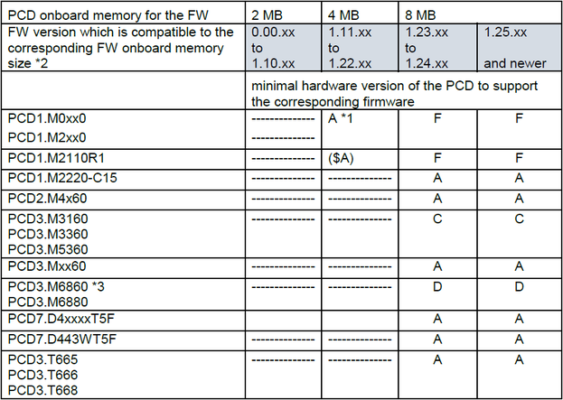
Which hardware revision of the PCD2.M5_ is needed for firmware 1.14.23? (FAQ #101490)
Even the firmware filename suggests hardware rev. 'D' is needed this firmware is suitable for revisions 'A' and later.
With PG5 2.0 the current production firmwares gets also installed on the computer. They are located in the directory
"c:\Program Files\SAIA-Burgess\PG5_20\FW\Classic\" or similar.
The filename for the PCD2.M5_ contains a wrong minimum hardware revision description and is named "PCD2M5xx0_1.14.23(HW min D).blk" by mistake.
So in contrast to the filename the firmware 1.14.23 is applicaple to PCD2.M5xx0 with hardware revision 'A' and later.
The filename will be corrected with the next service pack for PG5 2.0. -
What are the differences between firmware 1.10.51 and 1.14.23? (FAQ #101470)
In July 2010 the firmware 1.14.23 has been introduced into production for the PCD2.M5xx0 and the PCD3.Mxxx0. This FAQ lists the main differences between versions 1.10.51 and 1.14.23.
New features
please note that in order to take advantage of these new features PG5 2.0 SP1 (PG5 2.0.150) is required.- Increased amount of available flags (14335 instead of 8191), see FAQ 101447
- S-Web and FTP Server as well as the IP Enhancements (DHCP, DNS, SNTP and PPP) can be configured in the Device Configurator, see FAQ 101464
- Webserver access levels can now be configured in the Device Configurator (was before in the WebBuilder settings), see FAQ 101613
- IEEE floating point values can be displayed on the S-Web server (display format is “e”), see FAQ 101188
- Number of COBs increased to 32, see FAQ 101467
Main corrections
- SYSWR for DB backup failed after a lot of backups, see FAQ 101466
- STXT with more than 512 bytes sent a wrong text, see FAQ 101468
- The IP address for the Open Data Mode System Function “ConnectTCP” could not be given as constant
Hardware compatibility of firmware 1.14.23 with PCD3 systems
The firmware 1.14.23 requires a PCD equipped with 4 MB onboard flash. Therefore the minimal hardware versions for installing the 1.14.23 and later are:PCD Type Minimal hardware version for FW 1.14.xx PCD3.M5xx0 (not the PCD3.M5440)
PCD3.M6xx0, PCD3.M3330Hardware version D PCD3.M3020, PCD3.M3120 Hardware version E modification 4 8 (E 48) PCD3.M3230, PCD3.M5440 Hardware version D modification 2 8 (D 28) PCD3.M2x30 (WAC and Compact) Hardware version A (no restriction) PCD2.M5xx0 Hardware version A (no restriction)
For PCD3 systems older than listed the firmware 1.10.61 is the last firmware which can be installed on these systems. This firmware is and remains available on the support site in parallel to the 1.14.23.
Remarks- When updating from 1.10.xx
Please note that the user program as well as the communication settings are lost during the firmware update from 1.10.xx to 1.14.xx (or 1.16.xx) - BACnet applications
The BACnet firmware 1.14.26 is compatible to this new production firmware. Please download the latest BACnet firmware package for PCD firmware 1.14.xx from the support page (link below).
-
Why can't I send more than 512 bytes using the STXT instruction? (FAQ #101468)
In case a text with more than 512 bytes is sent with a firmware older than 1.14.23 the according text has not been sent correctly.
Symptom
When sending a text with a length of more than 512 bytes on a PCD3 or a PCD2.M5 with a firmware older than 1.14.23 the text which is sent is not correct.
In case the text to be sent contains sub-texts which are introduced using interpreted text (e.g. the $Lnnnn) and the final length to be sent is more than 512 bytes, the same phenomenon can be observed.
Solution
Please update the firmware of your PCD to version 1.14.23 or later. -
Can I have more than 16 COBs? (FAQ #101467)
Up to firmware version 1.14.23 the maximal amount of COBs (Cyclic Organization Blocks) has been 16. In firmware 1.14.23 the amoung of COBs has been increased to 32. Thus on PCD2.M5 and PCD3 and newer systems up to 32 COBs can be used (COB to 31).
Remark
Please note that PG5 2.0 Service Pack 1 (PG5 2.0.150) is required in order to program the COBs 16 and higher. -
Why is the error bit 7 or 8 set when I try to execute a "Backup DB to flash"? (FAQ #101466)
In some cases, usually after a lot of backups which have been executed, the error bit 7 (flash task already started) or 8 (flash error) is set with firmware older than 1.14.23.
Symptom
A backup DB to flash (IL instruction "copy TEXT/DB to flash card", SYSWR 3000 or 3100) fails and the error bits 7 and/or 8 are set. This error remains, even after waiting several minutes without re-attempting a backup to flash.
Solution
This problem is corrected in firmware 1.14.23 or later. Please update your PCD firmware in order to solve this problem. -
What are the differences between firmware 1.10.16 and 1.10.51? (FAQ #101422)
In May 2010 the firmware 1.10.51 has been introduced into production for the PCD2.M5xx0 and the PCD3.Mxxx0. This FAQ lists the main differences between these versions.
New features
- The Serial-S-Bus mode “Parity master” is now supported on all serial ports of the PCD, see FAQ 101103
Main corrections
- Increased stability for BACnet upload/merge (requires BACnet firmware version 1.10.50), see FAQ 101417
- Correction which avoids potential data loss on the SD cards when a card with more than 256 kBytes capacity is filled by 70%, see FAQ 101377
In case an SD card is used on the PCD, the update of the firmware to the version 1.10.51 is strongly recommended! - Avoided inter-character delay on port 2 and 3 (PCD2.M5) or 0 and 3 (PCD3) which could lead to communication problems, see FAQ 101382
- A Bus Error could occur in some specific cases, see FAQ 101418
- Reading Ni1000 sensors with a PCD2/3.W340 by the media mapping returned wrong values, see FAQ 101416
- Profi-S-I/O and Profibus DP Master did not work, see FAQ 101244
-
How to define a comma as separator in interpreted texts? (FAQ #101392)
For writing data to files on the PCD file system and for sending SMS or EMails it is possible to enter the content of medias (registers, flags etc.) into the text to be written or sent. This is done by placing e.g. a $R0100 into the text to be sent. At the time of writing, the "$R0100" will be replaced by the content of the register 100.
While in the beginning only points could be used as seperators in interpreted texts, it is also possible using the comma as separator with recent firmware versions. In this case, instead of a point a comma is to be used:
Firmware dependencies
The comma separator can be used starting with the following firmware versions:PCD system minimal firmware version PCD2.M480 1.08.53 PCD2.M5xx0 1.10.16 PCD3.Mxxx0 1.10.16 -
Potential data loss on SD cards bigger than 256 MBytes (FAQ #101377)
Under certain circumstances (if the file system is occupied by more than 70%) data losses on SD cards bigger than 256 MBytes have been observed.
Symptom
Under certain circumstances data losses on SD cards bigger than 256 MBytes have been observed. By analyzing these reports we have seen that in case more than 70% of the available memory on such a card is used it is possible that data is lost on the next power-up of the PCD or after the card has been re-inserted into the memory module holder (R600 / R6000) or opened by the SD Flash Explorer.
In case of many delete operations executed by the module the mentioned data loss can also occur if less than 70% of the available memory is used (due to the ware-out management of the SD card which varies the used memory areas).
Solution
An additional safety mechanism in the PCD firmware 1.10.51 as well as in the SD Flash Explorer in order to avoid future potential data loss on concerned cards has been implemented.
As soon as the system is rebooted (or the SD card is re-inserted into the R600 / R6000 mounted on a PCD with a new firmware versions) actions are taken in order to avoid the mentioned potential data loss.
The according firmware 1.10.51 (for PCD2.M5xx0 and for PCD3.Mxxx0 systems) with the new safety mechanism can be found on the support site www.sbc-support.ch.
In addition to the safety mechanism a new SD Flash Explorer version 2.0.215.0 features a “Backup” and a “Restore” feature which allows the creation of a backup of the file system.
This SD Flash Explorer can be downloaded from the support site from the section for the PCD7.R-SDxxx and will be distribued with the SP1 for PG5 2.0.
Remarks- Even if the file system on a SD card is already filled up by more than 70%, it is still possible to download the data over FTP as long as the PCD is NOT switched off. This method is recommended before updating the firmware in order to guarantee that no data is lost.
- SD cards delivered by Saia-Burgess Controls AG after week7 of 2010 contain a mechanism that avoids the above mentioned data loss (as long as the card is not formatted with a firmware older than 1.10.51).
-
Overview of the current production firmware versions (FAQ #101304)
This FAQ contains an overview over the firmware versions currently used in production (which means that this firmware version is installed in our production facility).
Firmware versions used in production
The following firmware versions are currently used in production. For more information regarding the relevant firmware, please refer to the version information document of the according page.
PCD firmware versionsPCD System Firmware Date of introduction Remarks PCD1.M1x0 0F1 April 2010 PCD1.M0xx0 1.28.51 April 2022 PCD1.M2xx0 1.28.51 April 2022 PCD1.M2220-C15 1.28.51 April 2022 PCD2.M150 0F1 April 2010 PCD2.M170 0F1 April 2010 required for PCD7.R400 delivered after April 2010 PCD2.M480 1.08.53 April 2010 required for PCD7.R400 delivered after April 2010 PCD2.M5xx0 1.24.69 August 2017 PCD2.M4x60 1.28.51 April 2022 PCD3.Mxxx0 1.24.69 August 2017 PCD3.Mxx60 1.28.51 April 2022 PCD3.M6860 1.28.51 April 2022 PCS1.Cxxx 0F0 March 2010
MB Panel firmware versionsPCD System Firmware Date of introduction Remarks PCD7.D4xx_ (QVGA) 1.10.60 December 2010 Corrects backlight problem of B&W versions PCD7.D4xxV (VGA) 1.24.50 May 2012 With support for S-Web Editor 5.15.02 PCD7.D412D (SVGA) 1.18.28 May 2012 12" SVGA MB panel PCD7.D4xxE 1.18.07.04 January 2012 S-Energy Manager, image version 1.08 PCD7.D443WTxR 1.28.04 November 2016 PCD7.D4xxxT5F 1.24.50 December 2015
RIO firmware versionsPCD System Firmware Date of introduction Remarks PCD3.T660 1.14.26 Aug 2010 this system is replaced by the PCD3.T665 PCD3.T665|T666 1.28.16 August 2017 PCD3.T760 1.020 April 2010 Profibus DP and Profi-S-I/O RIO -
What does "Saia PCD® COSinus" stand for? (FAQ #101297)
When working with PCD systems you will cross the expression "Saia PCD® COSinus" sooner or later. This FAQ explains what "Saia PCD® COSinus system" stands for.
The expression "Saia PCD® COSinus"
In general the expression "Saia PCD® COSinus" stands for PCD systems which are equipped with Freescale (previously Motorola) Coldfire CPU technology. The "non-Saia PCD® COSinus" systems from Saia-Burgess Controls AG are based on Freescale 68k CPU technology (e.g. PCS1, PCD2.M170 etc.).
The Coldfire CPU technology is a new and more performant CPU generation, new development is generally realized on Coldfire CPU (while the 68k CPUs still are available in parallel).
The first PCD system based on the Saia PCD® COSinus technology has been the PCD2.M48x. For this system the whole firmware has been re-written. The firmware of new systems is built up based on the firmware developed for the PCD2.M48x platform (having the same core modules). New firmware functionalities (e.g. Modbus which is implemented in the firmware) are basically designed for the Coldfire CPU technology and thus for Saia PCD® COSinus systems.
Saia PCD® COSinus based systems
The following list contains the main PCD systems which are based on Saia PCD® COSinus technology.- PCD3.Mxxx
- PCD2.M48x
- PCD2.M5xxx
- PCD7.D4xx
- PCD1.M2xx (currently under development)
Does this mean that all Saia PCD® COSinus systems support the same firmware features?
No! Although the same base modules of the firmware are used, it is depending on the PCD system whether a specific feature is supported or not. For example the http protocol is supported by PCD3 and PCD2.M5xxx systems, but not on PCD2.M48x. -
How to implement a software watchdog (FAQ #101285)
With an activated software watchdog the processor monitors itself and restarts the PCD in the event of a malfunction or a loop.
Description (extract from the hardware manual)
The hardware watchdog provides maximum security. However, for non-critical applications, a software watchdog may be suffcient, whereby the processor monitors itself and the CPU is restarted in the event of a malfunction or a loop.
The core of the software watchdog is the instruction SYSWR K 1000. When this is first issued, the software watchdog function is activated. This instruction must then be issued at least every 200 ms, or the watchdog will trigger and restart the controller.
Usage- Placing a "Watchdog"-FBox in a FUPLA-file is the easiest solution:
- Instead of using the FBox it is possible calling the Software Watchdog in IL (using the instruction SYSWR K 1000)
- Placing a "Watchdog"-FBox in a FUPLA-file is the easiest solution:
-
Why does the S-I/O communication no longer work on a PCD3 or a PCD2.M5? (FAQ #101244)
If there is a SIO-Master and a DP-Master configured the SIO-Master does not go in the "Operate" state to make the data exchange.
Symptom
It can happen with the firmware version 1.10.16 that a PCD3 or a PCD2.M5 does not work as SIO-Master if they are also DP-Master.
Solution
This behavior is solved with the version 1.10.51 or newer (the first version which corrected this situation was 1.10.20). Please update the firmware of your PCD in order to solve this issue. -
What is the "WebServer2" on Saia PCD® COSinus systems? (FAQ #101191)
The WebServer2 is a re-implementation of the previous WebServer on Saia PCD® COSinus systems and of course compatibel to the previous version.
History
The first implementation of a Web Server on PCD systems has been realized around the year 2000. With growing experience additional features and higher performance have been requested. In order to fullfil this requirement, the WebServer has been re-implemented (with the result of the WebServer2).
What is new in the WebServer2?
In general the WebServer2 is functionally compatible to the previous implementation. In addition the following new features are supported:- HTTP 1.1 support
- HTTP caching is supported. As result the in FAQ 100708 is no longer to be applied; It is recommended to enable the caching for the JVM (option "keep temprary files on PC") when working with the WebServer2.
Remark: If the caching is not enabled, you will not profit from the supported caching; it will then work as it has before with the previous WebServer. - Better performance
- Parallel acces to files is properly supported (acces is no longer interrupted if another client loads the IMaster applet)
- Multiple Web clients can access the Web Server on the same physical interface with (Ether-S-Bus or Profi-S-Bus)
- Easier understandable error messages
- When texts are entered, the length of the text is specified (and no longer filled up with space characters)
- The WebServer2 does provide more information on the default page and has a nicer look. By viewing this page it is easy figuring out whether the WebServer2 is running on a PCDView of previous WebServerView of WebServer2
Firmware (FW) supporting the WebServer2
The table below indicates the first firmware versions supporting the WebServer2. Systems not listed in this table do not feature the WebServer2.PCD system pilot FW version production FW version PCD2.M480 1.09.38*)-PCD2.M5xx0 1.09.38*)1.10.16PCD3 1.09.38*)1.10.16*) Please note that in the first pilot firmware not all features have been supported.
Remark
The only incompatibe difference between the previous WebServer and the WebServer2 concerns users that use the "HTML forms":- The previous Web Server used:
%%TAG% - The WebServer2 expects (the "value" is no longer automatically added by the Web Server):
value=%%TAG%
An example for the HTML forms on the WebServer2 can be found in the attached document.
-
Can I calulate with IEEE floating point values on a PCD system? (FAQ #101188)
Yes, a new set of instructions for calculation with IEEE floating point values (single and double) has been added to the firmware of PCD2.M480, PCD2.M5xx0 and PCD3.
Introduction
Motorola FFP (Fast Floating Point) has been used for floating point calculations since the beginning of PCD history. In order to simplify the interface against systems which do not support FFp but IEEE format for floating point values the instruction set of the PCD has been extended. All "twin" of all instructions available for the calculation with FFP values are now also available for IEEE calculations.
What are the instructions in detail?
Each of the existing instructions for FFP (the default) do also exist for IEEE Float and IEEE Double data.- For IEEE Float, precede the mnemonic with an 'E' character, for example EIFP, EFADD (instead of IFP or FADD) etc.
- For IEEE Double, precede the mnemonic with 'D', for example: DIFP, DFSUB.
Minimum Firmware (FW) requirement for this feature
System pilot FW version first production versionPCD2.M480 1.09.40-PCD2.M5xx0 1.09.401.10.16PCD3.Mxxx0 1.09.401.10.16PCD systems not listed in this table do not support this function.
Remarks- These instructions can only be used with PG5 2.0.
- There is also a new instruction for the conversion from IEEE single to IEEE double (and vice versa):
EFPD (single to double) and DFPE (double to single). These instructions are supported by firmware version 1.10.15 and later. - The instructions for convertig a IEEE double value to an integer value and vice versa (DFPI and DIFP) are working correctly starting with firmware 1.14.23.
- IEEE single values can be displayed by the S-Web Server using the format "e" (e.g. 172.16.1.127/cgi-bin/readVal.exe,e)
-
Can I read a value from a PCD text and copy it into a register? (FAQ #101187)
For "reading" a value from a PCD text (e.g. copying "1234" from a PCD text with content "The next number is: 1234" into a Register) a new System Function has been added for PCD3 and PCD2.M5xx0.
What does this System Function (SF) do?
The new function "S.SF.DBLIB.ReadANumberFromText" allows reading a number from a text and copy it into a register. Starting from a provided pointer, the next number will be searched and copied.
Where do I find the documentation for this function?
This function is documented in PG5 2.0. The easiest way to open the documentation is opening the SEdit, selecting the "SF DB Access Library" and hitting "F1":
Minimum Firmware (FW) requirement for this featureSystem Beta FW version first production versionPCD2.M5xx0 1.10.071.10.16PCD3.Mxxx0 1.10.071.10.16PCD systems not listed in this table do not support this function.
Remark
This feature can only be used with PG5 2.0. -
Is it possible to search an expression within a PCD text? (FAQ #101186)
For parsing a PCD text for a specific expression (e.g. finding "world" in a PCD text with content "Hello world") a new System Function has been added for PCD3 and PCD2.M5xx0.
What does this System Function (SF) do?
The new function "S.SF.DbLib.SearchText" allows searching a text for a specific expression. If this expression is found, the SF returns the position of the expression within the text.
Where do I find the documentation for this function?
This function is documented in PG5 2.0. The easiest way to open the documentation is opening the SEdit, selecting the "SF DB Access Library" and hitting "F1":
Minimum Firmware (FW) requirement for this featureSystem Beta FW version first production versionPCD2.M5xx0 1.10.071.10.16PCD3.Mxxx0 1.10.071.10.16PCD systems not listed in this table do not support this function.
Remark
This feature can only be used with PG5 2.0. -
Why do I sporadically get communication errors when connecting a PCD/PCS in "Secure S-Bus Data Mode"? (FAQ #101180)
In case a "non Saia PCD® COSinus" PCD or PCS1 system is connected with "Secure S-Bus Data mode" (e.g. over a serial cable or over modem) from time to time a telegram is not answered correctly.
Symptom
A PCD or a PCS connected with another system (e.g. PC or another PCD system) using the "Secure S-Bus Data mode" does not answer a telegram from time to time. This can e.g. be seen by a red LED on transmit or receive FBoxes (or in case a PC is used, by interpreting the tracewin files).
This phenomenon can be observed on PCD1.M1x5, PCD2.M150, PCD2/4.M170 and PCS1 systems (with firmware which are supporting the "Secure S-Bus Data mode"). Saia PCD® COSinus based systems (PCD2.M480, PCD2.M5xx0 and PCD3) are not concerned.
Reason
The reason for this behavior is that the PCD/PCS does not correcly answer telegrams where the sequence number in the secure S-Bus Data Mode header is 0xC5h. This is the case in every 255th telegram.
(The character "C5" should be replaced by "C5 01" but this is not done).
Solution
Please refer to the table below for firmware version which do correctly handle the "C5" and therefore the symptom described above is avoided.System Firmware PCD1.M1x5 0F0PCD2.M150 0F0PCD2.M170 0F0PCS1 0F0 -
The XOB 8 is no longer called on the systems Saia PCD® COSinus. (FAQ #101137)
The XOB 8 who is called when the firmware detects an invalid instruction (Invalid OPC) in the user program is no longer called on the systems Saia PCD® COSinus (PCD3, PCD2.M5, PCD2.M480).
On the new systems, the control of the Invalid OPC is executed at the startup during the precompilation. So the XOB 8 will never be called.
This new mechanism is implemented to increase the speed and the flexibility of the systems Saia PCD® COSinus. -
What criterias are to be fulfilled for sending e-Mails from the PCD? (FAQ #101054)
The PCD3 systems equipped with an Ethernet port and the PCD2.M5540 are able to send emails. But sending e-Mails is not only depending on the CPU itself.
The PCD3 systems equipped with an Ethernet port and the PCD2.M554x support SMTP (Simple Mail Transfer Protocol). Sending emails does not only depend on this feature but as well on the ISP (Internet Service Provider), the firewalls and router configurations between PCD and ISP.
The attached checklist with the criterias to verify with your provider and / or your IT support shall help to check whether sending E-Mail is possible. -
Why do I get a "68k add Error" when writing a text on the S-Web Server? (FAQ #101049)
When trying to write a text (with address higher than 4000) using the S-Web Server, the PCD system stopps working and in the PCD history a "68k add Error" is indicated.
Symptom
When trying to write a text (with address higher than 4000) using the S-Web Server, the PCD system stopps working and in the PCD history a "68k add Error" is indicated.
The following PCD systems are concerned:- PCD1.M1x5 with firmware version higher than 0B0
- PCD2.M150 with firmware version higher than 0E0
- PCD2/4.M170 with firmware version higher than 030
- PCS1.Cxx0 with firmware version higher than 0C0
Reason
This behaviour is not intended. Due to a problem in the firmware the write access fails.
Solution
This problem is solved in firmware version 0E6 (the version indication 0E6 is the same for all systems) which can be downloaded from the support site (www.sbc-support.ch). -
Why is the message: "Failed to get data on alarm.exe" displayed on the alarming page? (FAQ #100963)
This error message appears if the used firmware on the CPU does not support the "active and non ACK" filter for the S-Web alarming functionality (e.g. a PCD2.M150 with firmware 0D3).
Symptom
Instead of the alarm list of the S-Web alarming macro, the message "Failed to get data on alarm.exe" is displayed on the alarming page.
Reason
The reason is that the macro tries receiving the alarms filtered by the "active and not acknowledged" state of the alarms. This does only work if this feature is implemented in the according firmware.
Solution
Please update the firmware (FW) of your PCD system to the firmware supporting the according feature (see table below).System minimal FW PCS1.Cxxx 0E3PCD1.M1x5 0E3PCD2.M150 0E3PCD2/4.M170 0E3PCD2.M480 1.08.21*)PCD2.M5xx0 1.08.19PCD3.Mxxx0 1.08.23*)
*) On PCD3 and PCD2.M480 systems the "active and not acknowledged" filter has already been implemented in previous versions, but has been improved this indicated version. -
Is it possible reading the PCD "IP address" from the user program? (FAQ #100952)
Yes, this is possible by calling the system function (CSF) "IPGetLocalConfig".
Introduction
For having the possibility to read the current IP configuration from the user program, a specific System Function has been added to the firmware. This function does return the IP address, the subnet mask as well as the default gateway (each address in one register). The returned value contains the full IP address in one register (each byte or the register contains one octed of the IP address):
Example
This System Function is part of the IPD Library. In order to use these functions, the file "IPLib.inc" is to be included to the source file where the function is called. This can be done with the line:
$INCLUDE "IPLib.inc"
The IP configuration can then be read in th following way:STH F 0 ; only call the function DYN F 1 ; on a rising edge of F0 CSF H S.IPD.Library ; from the IPD library S.IPD.IPGetLocalConfig ; call the function "IPGetLocalConfig" R 0 ; (R) returned IP address R 1 ; (R) returned Subnet mask R 2 ; (R) returned Default gateway
Returned IP address (hex): 0xAC100179h
IP address in "Dot-decimal notation": 172.16.1.121 (0xACh = 172, 0x10h = 16, 0x01h = 1, 0x79h = 121)
Firmware versions supporting the GetLocalIPConfig
Please refer to the table below for the first firmware versions that support the "IPGetLocalConfig" function.PCD System minimal firmware version PCD1.M1x5 0E3PCD2.M150 0E3PCD2/4.M170 0E3PCD2.M480 1.08.21PCD2.M5xx0 1.08.19PCD3.Mxxx0 03C
Remark
The include file "IPLib.inc" from PG5 1.4.300 and earlyer versions needs to be updated in order to "know" this feature. Therefore please download the file "IPLib.inc" attached to this FAQ and replace the existing file from PG5 which is located in the "Libs/App" of PG5:
c:\Program Files\SAIA-Burgess\PG5 1_4\Libs\App\IPLib.inc -
How does the system watchdog work? (FAQ #100908)
In firmware version 1.08.xx for systems running the Saia PCD® COSinus firmware, the system watchdog has been introduced. If a PCD reboots because of the system watchdog, the message "SWTO ERROR" is entered in the PCD history.
What for is a system watchog?
The system watchdog is a security measure which avoids a situation where the system (PCD) is blocked and does not properly execute the program any more. If the OS (Operating System) is "locked" in a loop and does no longer properly execute its tasks (among others, the user program), the PCD is automatically re-started.
What does the system watchdog do?
The (internal) system watchog is configured directly on the CPU and will cause a re-boot if it is not triggered in a cyclic manner. Every reboot caused by the system watchdog is entered in the PCD history with the message SWTO ERROR (SWTO stands for System Watchdog TimeOut).
The behaviour after the automatic reboot caused by the system watchdog is depending on the software watchdog which can be programmed in the user program:- If the software watchdog in the user program is enabled, the PCD will automatically go in RUN after a reboot caused by the system watchdog.
- If no software watchdog is programmed in the user program, the PCD will go to "Halt" after it has rebooted because of the system watchdog.
Does the system watchdog conflict with other watchdogs?
No, the system watchdog does not conflict with e.g. the software watchdog programmed in the user program or with a hardware watchdog.
When has the system watchdog been implemented?
The system watchdog has been implemented in firmware version 1.08.xx. The first production versions for the relevant systems can be found in the table below:PCD system first production firmware with system watchdog PCD3.Mxxx0 1.08.23PCD2.M480 1.08.21PCD2.M5xx0 1.08.19
Remark
Note that the system watchog does not detect a bogus user program (e.g. an infinite loop) and therefore the usage of the software watchdog in the user program is still recommended. -
Why are broadcast telegramms not working anymore on the PCD3 or PCD2.M480 (FAQ #100798)
In firmware 03B and 03C an S-Bus broadcast telegram will block the communication interface until the next reboot of the PCD.
Symptom
When using firmware version 03B or 03C on either a PCD2.M480 or a PCD3.Mxxx0, the communication stops working after a sent broadcast. This only applies if the concerned PCD is acting as master on the S-Bus network.
This phenomenon occurs on S-Bus (Serial-S-Bus, Ether-S-Bus or Profi-S-Bus).
Reason
In firmware 03B and 03C an S-Bus broadcast telegram will block the communication interface until the next reboot of the PCD.
Solution
In order to resolve this problem, please update the firmware of your concerned PCD. -
New firmware version names for Saia PCD® COSinus systems (a.bb.cc) (FAQ #100741)
In order to simplify the interpretation of firmware versions and to avoid confusion regarding implemented features and bug fixes in different firmware versions, a new firmware version format for Saia PCD® COSinus based systems will be introduced.
Arguments for the new format
The new firmware version naming allows a clear and easy comparison between the different versions and their implemented features (PCD type specific) and bug fixes.
Questions like "Why is the Alarming functionality of the PCD3 Web Server implemented in firmware version $31 but not in version 031? - They both do have the same number..." should be past (however, if you're interested in the answer, please refer to FAQ100176)Format description
The new firmware version name does consist of a major version, a branch version and a minor version separated by a dot (.).
Note that the prefix characters “0”, “$” or “#” are no longer used in this notation.Concerned systems
The new firmware version format is applied to the systems based on Saia PCD® COSinus firmware (Classic and xx7). These are- PCD1.M2xxx
- PCD2.M48x
- PCD2.M5xxx
- PCD3.Mxxxx
- PCD7.D4xx (MB Panels)
While the firmware names for the MB Panels and PCD1.M2xxx do have this format from beginning, it was introduced on the PCD3 and PCD2.M480 systems with the firmware version after 03B.
Version flow example
Below an example for a version flow. If e.g. a bug is corrected in the version 1.06.01, also version 1.07.02 and all following 1.06.xx versions do/will have this correction implemented.
Version typesReleased beta- or maintenance versions (equivalent to the current “Bxx” or “#xx” versions).
Released Production versions (equivalent to the current “0xx” versions): These versions are introduced in the production.
New function versions (equivalent to the current “$xx” versions).
Compatibility with PG5
The new firmware names are fully supported by PG5 V 1.4.200:
Previous versions of PG5 will only show the first three digits of the firmware version (e.g. “106” instead of “1.06.08”). The full firmware version can always be read by displaying byte F0F0 in the “Online Debugger” (type DYF0F0 ): -
Different handling of the TBSY flag (in MC mode) between PCD3 / PCD2.M5 and older systems (FAQ #100655)
The diagnostic flag TBSY of the "Character Mode" (used for sending characters over a serial line) is not handled the same way on a PCD3 compared to "older" systems like e.g. PCD2.M170.
Symptom
If the relevant port is assigned in MC mode, the diagnostic flag TBSY is indicating that the serial port is busy sending characters. This is the case on e.g. a PCD2.M170.
This behaviour is not the same on a PCD2.M5xxx or a PCD3.Mxxxx, especially not when using a PCD3.F121 or a F2xx(x) modules. On a PCD3/PCD2.M5 the TBSY flag is not any more high during the whole time the port is busy. Instead, it is only high a short time at the very beginning of the send task.Reason
The reason for this difference is a new manner to access the UART of the port. On older systems the characters were directly written to the UART while on the PCD3 a buffer is placed in-between. Instead of indicating the "send-state" of the UART like on older systems, the TBSY represents the state of this buffer (the size can be found at the end of this FAQ) on the PCD3 or the PCD2.M5.Solution
This difference shouldn't lead to problem is most cases. However, in some applications the state of the TBSY is used to control e.g. the RTS signal of the line (using the instruction SOCL). In this case the communication (working on a PCD2.M170) won't work any more on a PCD3 or a PCD2.M5.
In this situation one of the following workarounds could be applied:- Instead of assigning the port in MC0 it could be assigned in MC4 (MC4 is usually described as "MC for RS485"). In this mode the UART is managing the RTS autonomously (and therefore there is no more need to set the RTS by the user program). Note that in this case the SOCL commands are to be removed from the program!
- The duration while the RTS is to be set could be calculated beforehand (based on the amount of characters to be sent) and loaded into a timer. While this timer is high, the RTS can be set using the SOCL command.
Note that this solution is not really a "nice" one and can only work with very low baud rates.
Notes
- All firmware versions of the PCD3xxx and PCD2.M5xxx do treat the TBSY as described in this FAQ.
- The buffer size is depending on the port used:
PCD3 port 1 and 2: 24 characters
PCD3 port 0 and 3: 2 characters
PCD2.M5 port 0 and 1: 24 characters
PCD2.M5 port 2 and 3: 2 characters
-
Booter update on PCD2.M150 (FAQ #100606)
This FAQ applies in case the booter of a PCD2.M150 needs to be updated.
How can a booter be upgraded?
There are mainly two ways how the booter of a PCD2.M150 can be upgraded:- A new firmware chip is burned with an EEPROM burner. In this case a *.hex file is written onto the flash chip in a tool like e.g. GALEP. The *.hex file contains a booter as well as a firmware for the PCD2.M150 (e.g. the firmware 0D3 and the booter 012).
- The other method is that the booter is downloaded directly onto the PCD2.M150. In this case some conditions need to be fulfilled: The currently installed booter must support an update of the booter on the present flash chip.
Flash chips used and the support of downloading the booter
- SST 39SF040 firmware flash
In case the firmware is stored on a flash chip from the manufacturer SST (not used in production any more) the minimal booter version for updating the booter is 010. See procedure below. - AMIC A29040 firmware flash
In case the firmware is stored on a flash chip from the manufacturer AMIC the minimal booter version for updating the booter is 013. If an older version of the booter is present, the new booter must be written by using an EPROM burner. - ATMEL AT49F040 firmware flash
The first versions of the PCD2.M150 were delivered with this chip. This chip does not support the update of the firmware or the update of the booter with PG5. A new firmware must be written by using an EPROM burner in every case.
How to find out the currently installed booter version?
The booter version present on your PCD2.M150 (firmware 0D0 or newer) can be read using the online debugger:
Type: D Y 800010 (Display bYte 800010)
The booter version will be indicated at the end of the line shown.
What can I do if I have a chip listed above but there is a too old booter installed
In this case, please download the hex file version of the firmware used in production from the product section "Programmable Controller" --> "PCD2" --> "Mxxx CPUs" --> "PCD2.M150". These hex files can be written to your chips using a suitable EEPROM burner like Galep.
Once this firmware has been written to your chips, the firmware update can be done from the firmware download tool from PG5 (*.blk files are to be downloaded). - A new firmware chip is burned with an EEPROM burner. In this case a *.hex file is written onto the flash chip in a tool like e.g. GALEP. The *.hex file contains a booter as well as a firmware for the PCD2.M150 (e.g. the firmware 0D3 and the booter 012).
-
Firmware download on a PCD2.M150 (FAQ #100598)
From firmware version 0D0 it is possible to download the firmware to the PCD2.M150. It is not any more necessary to write the firmware chips (Flash) on an EPROM burner.
Introduction
For an easyer firmware upgrade procedure the booter and firmware of the PCD2.M150 has been improved in a way that it is possible to download the firmware directyl with the PG5 firmware downloader. The minimal firmware version for enabling this firmware download is 0D0 (the accoring *.hex files do contain the appropriate booter version 010 or higher).Of course it is still possible to write the firmware flash on a EPROM burner as it is to be done for older versions.
In case your PCD is equipped with a firmware older than 0D0 (e.g. 0C4) you have to burn a new firmware chip (manufacturer either AMIC or SST) with a firmware 0D0 or newer. You can find these files as usual on the support site in the product folder of the PCD2.M150.Official introduction in production
The first official firmware supporting the download of a new firmware is 0D3. This firmware has been officialized and introduced into production in week 30 of 2006. The booter version installed with this firmware is 012.Firmware download procedure
As soon as you have installed the firmware 0D0 or higher, you can simply downlod a new firmware with the following procedure (given the installed chip supports the download of the firmware, see FAQ 100606).- Open PG5
- From the menu "Tools" select the "Online Configurator"
- In the Online Configurator click the button "Go offline" (for downloading the firmware PG5 must be offline)
- From the Online Configurator menu "Tools" select "Download Firmware"
- In the Firmware Download Utility click the button "Add" and browse to the new firmware for the PCD2.M150 (the file must have the extension *.blk). Make sure only this file is visible in the window. If there are other files, remove them with the button "Del".
- Click "Start" for starting the download
The file to be downloaded is a *.blk file which can be downloaded from the support site as well.Flash chips supporting the download of the firmware
There are several flash chips holding the frimware on the PCD2.M150. Unfortunately the first introduced chip does not support the download of the firmware. Below a list of the used flash chips:- AMIC A29040 (A29040B-70F)
This chip supports the download of the firmware. The download of the booter is supported from booter version 013 (to be installed together with firmware 0E3 hex files). - SST 39SF040
This chip supports the download of the firmware as well as the download of the booter*). - ATMEL AT49F040
This chip doesn't support the download of the firmware. For updating the firmware, the new firmware version has to be burned to the chip using an EPROM burner.
*) For updating the booter out of booter version 010, 011 and 012 the PCD must be set in the bootloader mode first.
-
S-Bus Slave on Port 3 doesn't work with FW 020 on the M480 (FAQ #100389)
If the Port 3 is initialized in mode S-Bus slave it won't work anymore with FW 020. The bug is corrected in FW Versions > 020 (#21) and did not appear in versions < 020.
-
lose Hardware settings after Firmware update (FAQ #100366)
check before Firmware download over a network TCP/IP or Modem:
before you update the PCD- firmware, check that your hardwaresettings and user program is stored in to the flash memory
PCD2.M170 with flash PCD7.R400
PCD2.M480 with flash PCD7.R400
PCD3.M5540 with flash PCD7.R500
PCD3.M3… onboard flash
Backup:project manager/online/ Flash Backup
-
FW depending differences in the handling of the diagnosic flags (FAQ #100321)
There are firmware depending differences in the handling of the Serial-S-Bus communication diagnosic flags TDIA and RDIA. Those flags are refreshed continuously by older FW versions but not by the Saia PCD® COSinus Classic PCD firmware (used for PCD2.M480 and PCD3 controllers).
Symptom
The diagnosic flags do indicate whether there has been a communication error. The flags are directly depending on the diagnostic register RDIA. If the RDIA holds any value not equal to 0, the according diagnostic flag is set.
The state of the diagnostic flags is refreshed every ms by conventional FW versions (used for PCD1, PCD2.M1x0, PCD4, PCD6).
The Saia PCD® COSinus Classic PCD firmware (used for PCD2.M480 and PCD3) does not any more refresh the diagnostic flags cyclically. On this FW, the diagnostic flags are only refreshed on a communication event (such as e.g. a SRXM instruction).Reason
Basically the diagnositc flags are refreshed by the communication routine of the FW. Conventional FW is polling the communication routine cyclically (every ms).
The Saia PCD® COSinus Classic PCD dosn't call the communication routine cyclically but only on interrupt (e.g. the communication instruction SRXM does generate such an interrupt). This means that the diagnostic flags are only refreshed on a communication event.
The advantage of this method is a minimized CPU load due to the communication task.Conclusion
This change of the behaviour of the diagnostic flags isn't conflicting with any description or manual. However, there could be some program code that bases on the automatic refres of those flags. In this case the code has to be adapted when intended to use on a PCD running Saia PCD® COSinus Classic PCD FW.
The adaption could be realized in the way that on reset of the RDIA (which has to be done anyways) also the diagnostic flags are reset. -
Incompatibility of old FW and new Profibus DP configurator (FAQ #100319)
The Profibus DP configurator of PG5 1.3 (older than SP1.3.120) does create configuration files that don't run on a PCD2.M110/120 equipped with FW 080 and older.
Symptom
The Profibus DP Module can't be initialised. The error LED is lit instead and "PROFIBUS FAIL 000" is entered in the History of the PCD. Profibus DB Master and Slave configurations are concerned.Reason
The reason for this problem is that the Profibus DP configurator (coming along with PG5 1.3.100 or SP1.3.110) will store the configurations in DBX 4. This address isn't available in FW versions up to 080 (since only 4 DBX are available, address 0 included).Solution
- Either update to the latest official FW for the PCD2
- Or Update to PG5 SP1.3.120 (or higher)
-
Which Flash chip to use for which usage? (FAQ #100309)
Some PCD types (Classic and xx7) have stored their firmware on 4 Mbit flash chips plugged on the main board. Further on the user memory/backup memory of many PCDs may be extended by mounting a flash chip. This FAQ contains a list of those memory chips in relation to the usage.
The possible applications for the 4 MBit flash chips
Usage of chip Chip type ordering number FW chip for PCD2.M150 A29040B-70F (AMIC) 4 502 7341 0 old:
ST39SF040-70 (SST) old:
AT49F040-70 (ATMEL) FW chip for PCD2.M127/157 (needs FW V3.103) A29040B-70F (AMIC) 4 502 7341 0 old:
ST39SF040-70 (SST) old:
AT49F040-70 (ATMEL) User memory for PCD1.M1x5 and PCD2 Classic (not M170 or M480) AM29F040 4 502 7224 0 Backup memory for PCD2.xx7 needs FW V2.410 AM29F040 4 502 7224 0 old:
AT29C040 4 502 7248 0 The possible applications for 1 MBit flash chips
Usage of chip Chip type Ordering number User memory for PCD1.M1x0, PCD1.M1x5 and PCD2 Classic (not M170 and M480) AM29F010 4 502 7141 0 Backup memory for PCD1.M137 and PCD2.xx7 AM29F010 4 502 7141 0
-
Error LED of PCD is lit! How to find the problem? (FAQ #100269)
There is an Error Led on nearly every PCD system that can indicate a problem on the system. Read this FAQ to learn more about the different reasons for a lit Error LED and how to find the problem causing the lit error LED.
What causes the Error LED to get lit?
There are different reasons for a lit error LED. The most common reasons are listed below:- A problem while assigning a communication port (e.g. missing communication module or wrong parameters)
- A problem while sending an S-Bus telegram (e.g. missing port assignation or invalid data array or media)
- Invalid mathematical operation (e.g. division by zero or value overflow after a multiplication)
- Index register overflow
How to find the problem in the code/configuration?
One fast way to find the problem is reading the history entries of the PCD. This may be done by using either the Online Configurator or the Online Debugger (type "Display History"). In the History some of the problems are listed explicitely (e.g. IPM not present) for further information regarding the History entries, please refer to the PG5 Help. The chapter "Messages" contains "Halt and History messages".
If only an "Error Flag" is mentioned the next task is to find the program part where the Error status-flag is set. This is to be done by using the Online Debugger:- Go online with your Fupla- or IL program.
- Open the Online Debugger and type "Restart Cold All CPUs".
- Still in the Online Debugger, type "Run Until Status-flag Error". As soon the Staus-flag "Error" is set, the PCD will be stopped. Therefore the Fupla Editor will jump to the page which actually is processed (only this page is part of the current Fupla file! If the Error isn't caused by this Fupla file, it will jump to any other page which doesn't cause the problem. Have a look at this page and the FBox with the "stop"-box on it and decide whether the problem could have been caused by this FBox!
If there isn't any FBox that could cause any problems mentioned above, repeat the procedure while beeing online with the next Fupla file of the CPU). - If you can't find the problem directly in a Fupla file, switch to the Online Debugger again. After having stopped, a line similar to the line written below will be shown:
*001234 STH I/O 48 A1 Z0 N0 P1 E1 IX COB2
This first number of this line indicates on which line of the code the problem happened: the last instruction BEFORE the line shown caused the problem (the error LED is lit after the problem). - Type "Display Program <line indicated -10> Count 15". Now you can see the instruction that caused the problem: Refer to the IL instruction Set (Online Help of IL Editor SEDIT) in order to figure out what this instruction exactly does.
If a SASI instruction causes the problem, check out the following possible reasons:
- The port is already assigned (have a look at the HW configuration and search for further SASI instructions by typing "Locate Instruction SASI" in the Online Debugger!).
Hint: Also have an eye on the SASI FBoxes you used as well as on the HMI Settings tab. - The port doesn't exist
- The SASI text isn't valid
- S-Bus support isn't enabled in the Hardware Settings but an S-Bus assignation was executed. This won't work because in this case the PCD doesn't have an S-Bus address (which is required for S-Bus communication).
If it seems as a mathematical operation caused the error, use the online debugger to run shortly before the problem-causing part of the code by typing "Run Until Instruction-Pointer Equals <instruction line shortly before problem-line>" (note that the instruction line must contain an instruction!). Once reached this line, type "sTep". In the Step-mode, you will see the contents of the PCD medias [brackets].
Remark:
The Error LED is lit in case the Status Flag E (Error status flag is set high) and no XOB 13 is programmed. In case the XOB 13 is programmed, the Error Led won't get lit but this XOB is processed immediately. -
What EPROM burner is recommended to create firmware chips for PCD's? (FAQ #100256)
We have made good experiences with the GALEP 4, for PCD1 FW together with the adaptor 210841. The local dealer for Switzerland is www.redacom.ch.
Order numbers for empty firmware chips:
PCD1.M1x0: 1x ASN 4 502 7178 (OTP27C4002), one time programmable
PCD1.M137: 1x ASN 4 502 7178 (OTP27C4002), one time programmable
PCD2.M110/M120: 2x ASN 4 502 7126 0 (27C1001-10, EPROM)
PCD2.M127: can be downloaded, refer to the product page on www.sbc-support.ch
PCD2.M150: 2x ASN 4 502 7341 0 (49F040 ,Flash-EPROM)
PCD2.M157: can be downloaded, refer to the product page on www.sbc-support.ch
PCD2.M170: chip soldered on the main board, the FW can be downloaded with PG5 *
PCD2.M177: can be downloaded, refer to the product page on www.sbc-support.ch
PCD2.M480: chip soldered on the main board, the FW can be downloaded with PG5 *
PCD2.M487: can be downloaded, refer to the product page on www.sbc-support.ch
PCD3.Mxxxx: chip soldered on the main board, the FW can be downloaded with PG5 ** Procedure to downlaod a firmware:
1) get the appropriate file from product page on the supportsite www.sbc-support.ch
2) open PG5 and go to the online-configurator; go offline
3) open the menu tools, download firmware
4) browse for the firmware file and start the download
5) load the HW configuration and the user program -
Baudrate limitation on serial ports (FAQ #100252)
Basically on PCD systems introduced before 2003 there are some restrictions to be considered about the maximum baud rate of serial communications.
Depending on firmware and hardware not all serial ports can be used at their theoretical maximum baud rate at the same time.
Systems introduced before 2003:
- All PCD1, PCD2 (except PCD2.M480), PCD4 and PCD6 as well as PCS1 classic contollers do have a baud rate limitation of 38.4 kB/s on each serial port.
For older firmware (FW) versions there is a further restriction since there is one UART responsible for two serial ports and this UART cannot handle baud rates of 38.4 kB/s on both ports at the same time. The port allocation of the UARTs is the following: first UART: port 0 and 1; second UART: port 2 and 3 etc.
This means that it isn't possible to set the concerned ports to
- 38.4 kB/s each
- one to 38.4 kB/s and one to 19.2 kB/s
- but it is possible to set one port to 38.4 kB/s and one port to 9600 B/s. - Due to more efficent port handling recent FW versions do have the following restriction (independent of production date of HW):
Amount of ports available divided by 2 equal amount of ports that can communicate at 38.4 kB/s. All the residuary ports do have a maximal baud rate of 19.2 kB/s.
In addition an UART of an PCD7.F5xx isn't able to handle 19.2 kB/s on one and 38.4 kB/s on the other port. But it is possible to assign both ports to 38.4 kB/s.
Systems introduced since 2003 (PCD2.M480 and PCD3.xxxx):
Due to faster hardware there are much higher baud rates possible on the serial ports (up to 115 kB/s)!
There is only one restriction regarding UART sharing left:
On a PCD7.F5xx it is not possible to communicate on one port at 19.2 kB/s and one the second port at 34.8 kB/s at the same time (but two times 38.4 kB/s is possible!).
This means that all ports may communicate at the maximum baud rate (which is specified in the technical information (TI) or in the manual) at the same time.FW versions that support the new port handling mentioned above:
For the following and newer FW version the following rule is valid:
Amount of ports available divided by 2 equal amount of ports that can communicate at 38.4 kB/s.
All the residuary ports do have a maximal baud rate of 19.2 kB/s.PCD system required FW version PCD1.M1x0 V081 PCD2.M110/M120 V090 PCD2.M150 V0C0 PCD2/4.M170 V010 PCD4.Mxx5 not supported PCD6.M1xx/M2xx not supported PCD6.M3x0 V040 PCS1.C8xx V090 - All PCD1, PCD2 (except PCD2.M480), PCD4 and PCD6 as well as PCS1 classic contollers do have a baud rate limitation of 38.4 kB/s on each serial port.
-
Communication interface isn't reset on SW watchdog restart with option XOB0 enabled (FAQ #100243)
Communication interfaces containing a co-processor aren't restarted after a restart caused by the software watchdog with the option "Execute XOB0". In fact only a restart cold will be executed but without resetting the communication modules.
This behaviour is a bug and will be corrected in the next FW version for the corresponding CPU. As soon as the new FW is built it will be available on the support homepage.
In the meantime it is recommended not to use the option "Execute XOB0" for the software watchdog. In this case the communication modules will be reset normally on software watchdog execution.
-
Software Watchdog mustn't be used with FW 0C1 on PCD2.M150! (FAQ #100218)
If once the Software Watchdog is configured on a PCD2.M150, the system can't be started any more until the FW will be changed to either an older version (not recommended) or to the latest version 0E3 (recommended)!
This problem is due to a too long starting sequence of the FW which will cause the Software Watchdog to restart the system right after its initial start. This causes the PCD not booting up at all any more.
In the concerned state, all LEDs (RUN, HALT and ERROR) are lit; the restart will be proceeded before the actual boot sequence indicated by the running LED's of the PCD starts.To solve this problem the FW chips have to be replaced. These chips either can be ordered at your SBC representative or the actually used chips can be rewritten using a EPROM burner such as GALEP IV.
Since the FW of a PCD2.M150 is written in Flash EPROMs, it can be ereased and reloaded with the hex files of the FW version 0E3 available on the Support Site www.sbc-support.ch or at your SBC representative. -
Firmware version naming of non-Saia PCD® COSinus systems (FAQ #100176)
Or "What is the difference between 0-, $- and #-firmware versions?". PCD firmware for non-Saia PCD® COSinus Systems (PCD1, PCD2.M1x0, PCD4, PCD6 and PCS) are named with 3 letters (e.g. 010, B0W or #31). This FAQ explains the meaning of these version and how to figure out which one is more recent.
The firmware version naming of non-Saia PCD® COSinus systems
In general the 3 letters (abc) are used for the following indications:- a
Definition of the kind version this firmware is. The possible versions are the following
- 0xx versions are "official production versions" (010 is the first official production version)
- Bxx versions are Beta versions which contain new features compared to the previous production version
- #xx versions are "customer bug fix versions" of an official production FW version.
- $xx versions (Pilot version) include new functionalities which are not yet fully tested. Therefore a $-version should only be used in field if the developement gives their ok! - b
The second letter defines the main production version (starting with 01x wich stands for first official production version, followed by 02x (where the 02x has important new features compared to the 01x version - c
The last letter is incremented for each build of the firmware (best observed for the bug-fix versions; #21 is based on the 020 firmware and contains corrections for the 020 firmware version)
To figure out which version the base version of a bug fix- or pilot version is, have a look at the second character of the corresponding version (e.g. the "1" of the 013). This character indicates the official production version on which the bug fix or pilot version is based on.
Examples
010 is the official production version
018 is the production bug fix version of 010; no new functions
#19 is a customer bug fix version based on 018 (and therefore also on 010); no new functions
$19 is a pilot version based on 010 with new functions. The bug fixes done for e.g. 019 probably aren't implemented in this version! (the new features will be added to the production firmware versions in 020 or later.
Remark
Early versions of the Saia PCD® COSinus systems (PCD2.M480, PCD3, PCD2.M5) up to 039 were named with this system as well. In order to reduce confusion concerning features of a firmware the new firmware naming a.bb.cc has been applied (see FAQ 100741). - a
-
Not all History entries can be found in the Online Help of PG5 (FAQ #100173)
Some history entries introduced in new firmware versions can't be found in the Online Debugger Help nor in the online help of the Online Configurator.
Below you can find recently introduced History entries that can't be found in the Help files of PG5 versions older than PG5 1.3:
History Entry Meaning Remark MEM-EXT. ERROR Extension memory corrupted Replaces "BAD TXT/DB TABLE" CONFIG TOO LONG HW setting to long to be put in EEPROM Replaces "BAD MODEM STRING" WATCHDOG FAIL Restart due to SW Watchdog was executed IPM NOT PRESENT There is an IP configuration but no IP module IPM DONT RESTART PCD has restarted but the IP module does not respond IPM HAS OLD FW The IP module FW is not compatible with the PCD FW IP FAIL SASITEXT There is an error in the SASI text IP FAIL SASI DBX There is an error in the node list configuration DBX IP FAIL NO IPM An IP function has been carried out, but the PCD has no IP configuration IP FAIL TOUT Incorrect timeout value in Ether-S-Bus master SASI text IP FAIL PORT Nbr Incorrect port number in Ether-S-Bus master SASI text Included text >3 Text nesting depth overflow SBUS PGU Error The SBUS PGU Port defined in the HW Settings isn't physically present
Error Messages concerning PCD1.M2, PCD2.M480, PCD2.M5xx0 and PCD3.Mxxx0 systems (SBC-NT)History Entry Meaning . Media corruption This message indicates that the onboard RAM has been corrupted (becaused of a discharged superCap, bad Battery or similar).
If this message is shown, all medias (R, C, F) are reset to 0, the clock is reset and the program is restored from the onboard flash (if possible).
This entry has been replaced in firmware version 1.10.04 by "Memory Lost nn"Memory Lost nn Replacement message for "Media Corruption", but with more detailed informaton why the user program was restored and the media reset (since FW version 1.10.04):
01: Bad or missing battery
02: Supercap voltage too low
03: Corrupted memory pattern/signature
04: RAM memory cleared by user (push button)
05: RAM and flash memory cleared by push button
06: Corrupted program headerNot RUN on xx7HW The HW is a xx/ type; the FW doesn't run the program on this HW SYS. TYPE ERROR The HW system type isn't correct Reg>4095 not sup The FW doesn't support more than 4095 registers SF NOT LOADED System function (CSF) isn't present CSF INV PAR NBR Invalide CSF parameter number DOUBLE TIME BASE Timebase defined more than once XOB Nbr to big XOB (Exception Organisation Block) number is too big COB Nbr to big COB (Cyclic Organisation Block) number is too big FB Nbr to big FB (Function Block) number is too big PB Nbr to big PB (Program Block) number is too big IST Nbr to big IST (Initial STep) number is too big ST Nbr to big ST (STep) number is too big TR Nbr to big TR (TRansition) number too big SB Nbr to big SB (Sequential Block) number too big FABINFO CRC FAIL Invalid CRC in the fabrication information. Please contact SBC SYSWDOG START Restart due to SW Watchdog executed NO COB No COB loaded EXTHDR EEPR FAIL Error in the EEPROM extended header IP SB GWY FAIL TCP/IP SBus gateway can't be initialised IP Ch xxx no mem No memory to open the channel on the TCP/IP Open data mode MODEM: UART fail UART doesn't accept the configuration MODEM: Reset fail Error on the modem reset command MODEM: No modem No modem or defective modem equipped on the port MODEM: Init fail Error on modem initialisation MODEM: ERROR??? Unknown modem error DIFF CFG Ch x Different configuration on Profi-S-Net port x. Verify the configuration of the port PS FAIL SASI DBX Error in the node list configuration DBX PS FAIL TOUT Incorrect timeout value in Profi-S-Bus master SASI text PS FAIL SAP Incorrect SAP number in Profi-S-Bus master SASI text PS FAIL SASITEXT Error in SASI text PSM NOT PRESENT Profi-S-Net (Profibus) configuration but no Profi-S-Net (Profibus) existent PSBus GWY FAIL Profi-S-Bus GWY can't be initialized PSBus PGU FAIL Profi-S-Bus PGU port can't be initialized
SWTO ERROR System Watchdog Timeout Error, see FAQ 100908 and 101069 BUS ERROR Internal memory access failed. Please contact your local support team, see FAQ 101069 TCPS ERROR TCPIP-Stack crash. Please contact your local support team
KRNL ERROR Internal task overload. Please contact your local support team, see 101069 BACnet incompatible FW The BACnet firmware found on the PCDx.R56x module is not compatible with the PCD firmware. Please update the BACnet firmware (see FAQ: 101010)
This message is only given with firmware version 1.10.16 and later.Bnt FAIL TL00001 An error occurred in relation to the BACnet configuration. Please refer to FAQ 101436. MANUAL HALT Indication that the PCD has been halted by pushing the Run/Halt button (implemented in firmware 1.14.23 and later) EXT DEVICE FAIL This message can be generated by PCD systems with FW 1.10.xx; The message is wrong and should be "31 CALL LEVELS".
It indicates a too big nesting level of FB/PBs (if XOB 10 is programmed, it is called in this case)RESISTERS FAIL The termination resistors of port 3 of a PCD3.M5340 can not be activated due to a firmware restriction, see FAQ 101722. INVALID PERI DBXHardware configuration contains errors (e.g. peripheral addresses, modules not supported by the firmware) -
Why is the instruction DSP not supported on Saia PCD® COSinus systems? (FAQ #100034)
The IL instruction DSP (display value on PCD7.F530 display) is not supported on Saia PCD® COSinus systems. When downloading it to a Saia PCD® COSinus system, the PCD will not go in RUN and give an error message such as "Invalid instruction" (e.g. a PCD2.M480), "Precompiler error" or "Invalid OPCODE" (on a PCD3.M5xx0 with firmware 1.10.16).
Why is the DSP instruction not supported on Saia PCD® COSinus systems?
Since it isn't allowed or even possibe to mount a PCD7.F530 card on a Saia PCD® COSinus system (e.g. a PCD2.M480, a PCD2.M5xx0, a PCD3 or a PCD1.M2xx0) the instruction for accessing the display of the PCD7.F530 is not supported by the CPU.
Remarks- The PCD7.F530 can't be mouned on a PCD2.M170 or on a PCD2.M480 because it could cause a short circuit on the internal bus connector placed right under the slot B1.
- If a user program containing a DSP instruction is downloaded the PCD2.M480 won't run the program and the error message "Halt reason: invalid instruction" will be entered in the CPU's History.
Communication / LON (FTT10)
-
Are the LonWorks devices PCD2.F240, PCD3.F2400 and PCD7.R582 still available? (FAQ #102064)
No, the LonWorks devices PCD2.F240, PCD3.F2400 and PCD7.R582 are no longer available.
The production of the LonWorks interface devices PCD2.F240, PCD3.F2400 and the LonWorks memory device PCD7.R582 was discontinued at the end of 2021 and the devices are no longer available.
As a replacement, we recommend the usage of BACnet.
-
LON Work: how many variables SNVT can be used on a PCD/PCS ? (FAQ #101296)
It is depending of the PCD/PCS used, the rest of the programme and of the memory available:
PCD2.M170/M150 until1000, advised 500 -700
PCD1,PCS1 advised maximum 400-600
When Extended Memory isn't used (not advised du to the speed) we can used normally 50 - 150 SNVT. -
Can I run BACnet and LON on the same PCD at the same time? (FAQ #101216)
In the system catalogue there is a schematic of a PCD connected to a BACnet/IP network which could lead to a missinterpretation. Although BACnet is supported by a PCD3 or a PCD2.M5xx0 and LON on IP will be suppored in future, it won't be possible to run both stacks on the same PCD at the same time.
Why is it not possible to run BACnet and LON at the same time?
This limitation is caused by the rather high usage of ressources (performance and memory) from both these firmware extensions. While there is no problem to run one of these firmware extensions, the currently available PCD systems do not support both firmware extensions at the same time.
It is intended to provide a solution for BACnet and LON on the same PCD but this requires a new PCD system in future.
Why is this schematics printed in the System catalogue?
The aim of this schematic is to show that both protocols are supported, but not to indicate that both protocols can be used at the same time. If the PCD is running the LON stack, the other communication could e.g. be Ether-S-Bus.
How can I realize a gateway from BACnet to LON with PCD systems?
The currently only solution is the realisation with two systems, which could e.g. be connected with Ether-S-Bus. -
Why it’s not possible to make the binding with the LonMaker to a PCS1? (FAQ #101132)
If a PCS1 does use at the same time a serial communication with > 9’600 baud and the user wants to make a binding with the LonMaker then it’s possible that the binding will not succeed and on the LonMaker there is an error message:
“The device is application less or is not associated with a program record”
To solve the problem and to be able to make the binding either you have to switch off the serial communication or to use a baudrate <= 9'600 baud.
The reason of the problem is, that the PCS1 has not enough CPU power to perform simultaneously a Lon binding and a serial communication with > 9'600 baud.
-
How to configure a LON interface on a PCD1 / PCD2? (FAQ #101075)
The PCD must be equipped with a PCD7.F8xx module and RAM is to be mounted on the memory socket, with the "memory use" set to RAM (the binding does not work with a Flash).
The RAM Text and RAM DB have to be set to the following range:
- PCD1: 2000-2499, 2500-2599
- PCD2: 4000-4499, 4500-4999
If 1 Mbit RAM is used the user memory should soon be too small, it is recommended to use 4 Mbit RAM.
For a PCD1 we recommend to use maximal 400-600 SNVT.
For other PCD the theoretical limit is 4095 SNVT.
How to save the binding in a Flash?
Follow these steps:
¨ Bind the network using RAM on all PCD
¨ Execute an upload dBx and rebuild (all)
¨ Replace the RAM with flash on all PCD at wish
¨ Download the program again, this goes now in flash
PCD2 / M1xx
-
On a PCD2.M4560 or PCD3.M5560, why the measured PT100 temperature values are not correct if the PT100 sensors are connected to PCD2.W220Z18 or PCD3.W220Z18 modules? (FAQ #102052)
If the PCD2/3.W220Z18 card is plugged in to a ‘Power PCD‘ or a PCD2.C1000 or PCD2.C2000 and if all 8 analog inputs channels of the PCD2/3.W220Z18 module are connected to 8 PT100 sensors then the measured PT100 temperature values of the 8 channels are not correct.
‘Power PCD’s’ are:
- PCD1.M2x20, PCD1.M2160, PCD1.M2220-C15
- PCD2.M5540, PCD2.M5440, PCD2.M4160, PCD2.M4560
- PCD3.Mxx60
To solve the issue, use and connect only up to 7 PT100 sensors to the PCD2/3.W220Z18 or do use a PCD2/3.W350 module, if all 8 PT100 are needed.
On the ‘old’ PCD’s like PCD2.M170 or PCD3.M5540 the PCD internal power supply V+ was at 24V
On the ‘new’ ‘Power-PCD’s’ and the PCD2.C1000 and PCD2.C2000 the V+ is 16,5V
The electrical design of the PCD2/3.W220Z18 was done in that the way, that the internal power V+ of 24V was required to handle all 8 PT100 channels.
Since the ‘Power PCD’s’ and the PCD2.C1000/C2000 have a V+ of 16,5V the driver on the PCD2/3.W220Z18 don’t have enough power to handle all 8 PT100 signals correctly.
To solve the issue, use and connect only up to 7 PT100 sensors to the PCD2/3.W220Z18 or do use a PCD2/3.W350 module, if all 8 PT100 are needed.
-
Why do the output of the PCD2/3.W6x5 not deliver stable signals? (FAQ #102014)
Depending of the hardware version of the W6x5 module and the I/O slot where the W6x5 module is plugged in, it’s possible that the analog output signal supplied from the W6x5 is not stable and is oscillating.
Symptom
The outputs of the PCD2/3.W6x5 do not deliver stable signals when placed on I/O slot 15 if hardware version B of the W6x5 is used.
If FBoxes are used for writing to the outputs, the FBox indicates temporarily an error.Reason
The W6x5 modules with hardware version B are not correctly handling the Watchdog output (O 255).
Note that this is only the case if the module is placed on I/O slot 15 (base address 240). On all other slots the modules work correctly.Solution
This problem is solved with hardware version A or C and newer of the PCD2.W6x5 or PCD3.W6x5 respectively. -
Why is the modem "MDLS144 onbit" no longer working on a new PCD? (FAQ #101718)
If the "MDLS144/288 Data9600 onbit" modem is connected to a "non Saia PCD® COSinus" system (PCD1.M1, PCD2.M1) then it's possible to establish a modem connection to those systems but if the same modem is connected to a "Saia PCD® COSinus" System (PCD1.M2, PCD3, PCD2.M5) then it isn't possible to establish a connection.
The reason of this behavior is the difference how the FW of the PCD does handle the modem.
In general the FW does send the as first step the "modem reset sting" and after this the FW does check the status of the DSR / CTS signal before in a second step the "modem initialization string" is send to the FW.
- On the "non Saia PCD® COSinus" systems the DSR or the CTS signal have to be high before to go to the second step.
- On the "Saia PCD® COSinus" systems the DSR and the CTS signal have to be high before to go to the second step.
Solution
To use the "MDLS144/288 Data9600 onbit" modem on "Saia PCD® COSinus" systems its necessary to set the DSR to high during the first step of the modem initialization.
To do this it's necessary to adapt the "modem reset sting" on the device configurator/HW-settings on Saia PG5® .
The "modem reset string" has to be changed from:
AT&F\r
to:
AT&F&S0\r
Remarks
The "modem initialization string" remains the same.
The modification could be used on "Saia PCD® COSinus" system as also on "non Saia PCD® COSinus" systems. -
Until when can a PCD2.M120 be reparied? (FAQ #101482)
The production of PCD2.M120 systems has been discontinued by the end of 2009. As possible replacement a PCD2.M150 or a PCD2.M5xx0 can be used.
The PCD2.M120 can be repaired until the end of 2014 (five years after the phase-out).
-
Why do I get a "DUART HW ERROR" on PCD2.M150 after restart? (FAQ #101395)
Communication on port 3 (PCD2.F520) during startup can lead to a DUART HW ERROR on the PCD2.M150
Problem
If there is a communicatin running on port 3 during startup (e.g. an OPC server which is polling data from the PCD), it can happen that the PCD goes in HALT with a DUART HW ERROR on startup.
Reason
Due to a firmware problem, the communication on port 3 can cause problems during the startup procedure.
Solution
The problem was corrected in FW 0F1 or later for the PCD2.M150. If you are concerned contact your support for the bugfix firmware. Note that the problem only occurs on startup. -
Why does the IP communication not work with firmware 0F0? (FAQ #101384)
Due to an error in the firmware 0F0 the IP communication does not work on the following systems:
PCD1.M1x5, PCD2.M150, PCD2.M170
Symptom
The IP communication does not work (and the firmware 0F0 is installed on the PCD). When going online over Socket this leads to an 68k Address Error and the CPU goes in HALT.
Reason
There is an error in the firmware 0F0 which leads to this problem.
Solution
Please update to firmware version 0F1 which is available on the support site.
In case you do not have access to the internet, it is also possible downgrade to a firmware from before 0F0 (e.g. 0E6).
Remark
The firmware version 0F0 has been introduced to the production in February 2010 and has been available on the support site since March 2010 until April 2010 (release of the 0F1). -
Why does my PCD1 no longer start (due to a "Text segment error") after downloading a project with PG5 2.0? (FAQ #101379)
On PCD1.M1x0 or a PCD2.M110/120 with old firmware version the CPU won't go in run anymore after downloading the project with PG5 2.0.110.
Symptom
As soon as the program is downloaded with PG5 2.0.110 the PCD1 (or a PCD2.M110) does not go in run anymore. The error message is "Text segment error" or similar.
Reason
Old firmware versions do not support the DBX (e.g. the one containing the TCP/IP Settings table) created by PG5 2.0.110.
Solution
The solution is either to update the firmware to the actual version found on the support site or to modify the "*.saia5pj" file according to the following instruction:- Close PG5 2.0
- Open your project under c:\Documents and Settings\All Users\Saia-Burgess\PG5_20\Projects\
- Open the file "Projectname.saia5pj" with a text editor like e.g. TextPad
You will see the following structure (or similar):
[Project]
FileRevision=2
UserName=SBC TCS-Support Murten
PG5Version=V2.0.110.10
PatchVersion=5
Name=Project17
Description=
DownloadAllOptions=0xFFFFFFFF
NumberOfCpus=1
LastActive=Device1 - Add the line: NoTcpipDbxFiles=1
Afterwards it looks like:
[Project]
FileRevision=2
UserName=SBC TCS-Support Murten
PG5Version=V2.0.110.10
PatchVersion=5
Name=Project17
Description=
DownloadAllOptions=0xFFFFFFFF
NumberOfCpus=1
LastActive=Device1
NoTcpipDbxFiles=1
[LibraryFiles]
NumberOfLibs=-1
[CommonFiles]
NumberOfFiles=0
[CPU1]
Path=Device1
DownloadSeq=1
After this modification you can open PG5 2.0110, execute a "rebuild all" and download the project again. Now the CPU goes in run.
Remark
PG5 2.0 SP 1 will no longer generate the DBX in question. The SP1 will presumabely be released end of March 2010. -
Firmware dependencies for the "DB Access Library" (FAQ #101372)
The System Function (SF library) "DB Access Library" allows e.g. copying texts into text or searching an expression within a text. These features have not been present in the first firmware version, and not all featurs are available on all PCD systems. Therefore please refer to this FAQ for the firmware dependency information.
What are the functions of the "DB Access Library"?
The System Function (SF library) "DB Access Library" allows e.g. copying texts into text or searching an expression within a text. The library consists of two parts, where the second part (including e.g. the SearchText function which allows sarching an expressino within a text) is only supported by Saia PCD® COSinus Systems (PCD2.M5, PCD3).
A detailed description of the functions can be found in the context menu of the "Function selector" from the IL Editor from PG5 2.0:
Firmware dependencies
The first part of the new "DB Access Library" consists of the following functions and is supported by the following PCD systems (systems not listed in the table do not support these features):
Functions- CopyTextBytes
- CopyBytes
- CopyDBBytesToR
- CopyRToDBBytes
- GetDBItem
- InitDBBytes
- InitDBItems
PCD System Firmware version PCD1.M1x5 0F0PCD2.M150 0F0PCD2.M170 0F0PCD2.M480 1.08.21PCD2.M5xx0 1.08.19PCD3.Mxxx0 1.08.23PCS1.Cxxx 0F0
Functions
The following functions are only supported on Saia PCD® COSinus Systems but not on systems like the PCD2.M150, M170 etc.- SearchText
- ReadANumberFromText
- CopyNBytesFromTextToText
- CopyAValueFromRKToText
- CopyBytes
PCD System Saia PCD® COSinus firmware version PCD2.M5xx0 1.10.16PCD3.Mxxx0 1.10.16
Remark
The function "CopyTextBytes" (copy one text into another, and thereby replacing $D, $H, $Rnnnn with date, time, register contents etc.) has already been supported by firmware versions before the ones listed in the first table; for more information please refer to FAQ 100886. -
Meaning of the error codes for DB backup to flash (FAQ #101284)
With the function codes SYSRD K 3000 or K 3100 it is possible to read the flash status (to check whether the flash is ready for backing up extension memory to flash).
Not all return values are mentioned in the manual versions until version 9.
Read Flash Status
Reads the Flash status and stores it in the ACCU and a Register with a SYSRDSYSRD K 3000 ;for PCD with FlashCard K 3100 ;for PCD Onboard Flash (PCD3 and PCD2.M5)
Result- If the ACCU is set Low and the return value in the register is 0 --> OK
- If the return value in the register is not 0 --> please refer to the list of status bits below for the reason why the flash can not be used.
- If the ACCU is set High --> if the Flash is busy and SYSWR was not executed.
The Error Flag is set if there is an error. See status bits for details. The destination register contains the status bits (description below)
Status bitsBit Description Cause 0No flash No flash is fitted 1No header config There is no header/user program copied on the Flash Card 2SYSWR not enabled The DB/Text mode is not enable (memory allocation) 3DB/Text does not exist Incorrect DB/Text number 4DB/Text size is not equal DB/Text size is different, has been changed 5Restored DB/Text on FlashCard were restored because an error was detected 6Buffer full To much DB/Text are saved, memory is full 7Already started Last SYSWR command was not finished before a new one
was started (For PCD3 and PCD2.M5 please read FAQ 101466, too)*8Flash error No backup DB is configured on the flash or on the SRAM.
Impossible to access the flash, the bit is updated during
the "initializing backup" or the "copying DB to flash. (For PCD3
and PCD2.M5 please read FAQ 101466, too)*9Flash busy Another job is working on flash *10DB size error DB size is zero. The bit is updated during the backup and restore DB 11..15Not used *16Header different The "User Program Backup Size" of the Flash is different from SRAM. The bit is updated during the "initializing backup" process. *17No flash card Flash card is not present. The bit is updated during the "initializing backup" process. *18No flash free The "User Program Backup Size" >= "User flash size". The bit is updated during the "initializing backup" process. 19...31(for future use)
* not used by PCD2/4/M170
-
Is Modbus supported by Saia PCD®s? (FAQ #101270)
Yes, Modbus is supported by the firmware of recent Saia PCD® systems (on all ports, including the ones on F2xx modules since beginning of 2011) or by a dedicated FBox driver.
General
There are two possibilities to use Modbus on SBC CPUs (Classic versions).- The new FBox library for Modbus "Modbus SBC Version" which takes advantage of the Modbus implementation directly in the Saia PCD® COSinus firmware.
Available for PCD1.M2, PCD3 and PCD2.M5 with firmware version 1.10.16 or more recent (for using on F2xx modules, in minimum FW 1.14.23 is required). - The Modbus FBox Library from our partner ENGIBY which is available since several years (www.engiby.ch) and supported also by PCD systems previous to the PCD3, PCD2.M5xxx and PCD1.M2xxx families (e.g. PCD2.M1x0, PCD2.M480 or PCD1.M1xx).
Remarks
- In order to use the firmware implementation of Modbus on PCD2.F2xxx or PCD3.F2xx modules, the following prerequisites need to be fullfilled:
- minimal PCD firmware: 1.14.25 (1.14.23 does support the F2xx modules, but
communication errors can occur)
- minimal hardware version of the F2xx(x) module: version D (delivered since beginning 2011) - The FBoxes for "Modbus SBC Version" are available for download from the support site since July 2009.
In PG5 2.0.110 and later the "Modbus SBC Version" is installed by default. Please note that a licence is required for this library.
- The new FBox library for Modbus "Modbus SBC Version" which takes advantage of the Modbus implementation directly in the Saia PCD® COSinus firmware.
-
"Send SMS extended" FBox and PCD1.M1x0 and PCD2.M110/120 (FAQ #101163)
The FBox "send SMS" now supports the funktion "$-commands in text" (which is set default "Yes") which is not supported on PCD1.M1x0 and PCD2.M110/PCD2.M120.
Symptom
Only empty texts are sent in SMS messages if the option "$-commands in text" is set to "Yes" and a PCD1.M1x0 is used. While sending the SMS message, the error led of the PCD is lit.
Reason
The feature "$-commands in text" is not supported by the PCD1.M1x0 and the PCD2.M110/120.
Please refer to FAQ 100786 for detailed list of PCD systems and firmware versions supporting the "$-commands in text".
Solution
For PCD1.M1x0 set the "$-commands in text" funktion on "No".
Remark
PCD1.M1x5 do support "$-commands in text". -
RAM chip types to be used as user memory on a PCD1.M1xx or PCD2.M1xx (FAQ #101100)
The memory capacity for the user program of some PCD1 or PCD2 types can be extended by plugging an additional RAM chip. This FAQ lists the chip types which have been tested for the use on a PCD1 or a PCD2.M110, PCD2.M120 or PCD2.M150.
Please refer to the table below for the chip types to be used as user program extensions:
Chip size Chip type ordering number SRAM 1 MBit (128 kByte) 70ns BS62LV1025 PC-70 4 502 7013 0 LP621024D-70LL SRM20100LLC70 HY628100ALP-70 GM76C8128CLL-70 MEL M5M51008BP-70L SRAM 4 MBit (512 kByte) 55ns BS62LV4006PC P55 4 502 7175 0 BS62LV4007PC P55 -
What is the minimum distance between PCD2.Mxxx CPUs and PCD2.C1xx extension rack? (FAQ #100892)
Due of the housing of the connector of the PCD2.K1.. extension cable a minimum distance of 6 cm is required between the PCD2.M… CPUs and PCD2.C1.. extension rack, if the extension rack PCD2.C1.. is placed on the right side of the PCD2.M… CPU.
-
Is possible to use two TCP/IP modules on a PCD CPU? (FAQ #100785)
Yes, the PCD2.M480 is able to handle two TCP/IP (PCD7.F655) modules.
If there is the need to have two independent TCP/IP modules on one PCD, then you have to use the PCD2.M480 CPU. On the PCD2.M480 it is possible to install two PCD7.F655, one on the emplacement B1 and one on the emplacement B2.
The PCD2.M480 does support the routing mechanism of TCP/IP request between the two cards only for the direction:
TCP/IP card on emplacement B1 to TCP/IP card on emplacement B2. -
Firmware download on a PCD2.M150 (FAQ #100598)
From firmware version 0D0 it is possible to download the firmware to the PCD2.M150. It is not any more necessary to write the firmware chips (Flash) on an EPROM burner.
Introduction
For an easyer firmware upgrade procedure the booter and firmware of the PCD2.M150 has been improved in a way that it is possible to download the firmware directyl with the PG5 firmware downloader. The minimal firmware version for enabling this firmware download is 0D0 (the accoring *.hex files do contain the appropriate booter version 010 or higher).Of course it is still possible to write the firmware flash on a EPROM burner as it is to be done for older versions.
In case your PCD is equipped with a firmware older than 0D0 (e.g. 0C4) you have to burn a new firmware chip (manufacturer either AMIC or SST) with a firmware 0D0 or newer. You can find these files as usual on the support site in the product folder of the PCD2.M150.Official introduction in production
The first official firmware supporting the download of a new firmware is 0D3. This firmware has been officialized and introduced into production in week 30 of 2006. The booter version installed with this firmware is 012.Firmware download procedure
As soon as you have installed the firmware 0D0 or higher, you can simply downlod a new firmware with the following procedure (given the installed chip supports the download of the firmware, see FAQ 100606).- Open PG5
- From the menu "Tools" select the "Online Configurator"
- In the Online Configurator click the button "Go offline" (for downloading the firmware PG5 must be offline)
- From the Online Configurator menu "Tools" select "Download Firmware"
- In the Firmware Download Utility click the button "Add" and browse to the new firmware for the PCD2.M150 (the file must have the extension *.blk). Make sure only this file is visible in the window. If there are other files, remove them with the button "Del".
- Click "Start" for starting the download
The file to be downloaded is a *.blk file which can be downloaded from the support site as well.Flash chips supporting the download of the firmware
There are several flash chips holding the frimware on the PCD2.M150. Unfortunately the first introduced chip does not support the download of the firmware. Below a list of the used flash chips:- AMIC A29040 (A29040B-70F)
This chip supports the download of the firmware. The download of the booter is supported from booter version 013 (to be installed together with firmware 0E3 hex files). - SST 39SF040
This chip supports the download of the firmware as well as the download of the booter*). - ATMEL AT49F040
This chip doesn't support the download of the firmware. For updating the firmware, the new firmware version has to be burned to the chip using an EPROM burner.
*) For updating the booter out of booter version 010, 011 and 012 the PCD must be set in the bootloader mode first.
-
Is it possible to download an xx7 firmware to a classic PCD and invers? (FAQ #100557)
In some cases it is the same hardware, but due to the fact that the system contains a system ID written in EEPROM we can not guarantee that a xx7 PCD works properly with Classic firmware and invers.
Therefore it is not possible to download a Classic firmware to Classic PCDs and xx7 Firmware to xx7 PCDs.
General
A PCD CPU is bought as xx7 system or as Classic system. As described above, the possibility of a conversion is not guaranteed or offered by Saia-Burgess Controls AG.
There is no service "Convert from xx7 to Classic" or similar available at the repair service.
Additional details- PCD2.M1xx, PCD1.M1xx
The xx7 hardware is not identical to the classic PCD hardware, as result it can not be converted by a firmware change. - PCD2.M5, PCD2.M480 and PCD3
While it could be possible to run a Classic PCD as xx7 PCD (depending on the hardware type etc.), it is e.g. not possible to load a Classic PCD if it was bought as xx7 system (because in this case PG5 will not accept downloading the hardware configuration as the system ID is not correct).
- PCD2.M1xx, PCD1.M1xx
-
Can I use the same GSD File for PCD2.M170 as for PCD4.M170 (FAQ #100412)
No, the GSD-Files are different. They have a different identification. The PCD2.M170 needs the GSD-File PCD2_Slave (SAIAcd20.gsd), otherwise the PCD4.M170 needs the PCD4.M170_Slave (SAIAcd40.gsd)
-
Functional limitation regarding the use of the modem library (FAQ #100392)
There is a functional limitation in the following firmware versions:
PCD1.M1x0: 083
PCD2.M110/M120: 096
PCD2.M150: 0C4
PCD2/PCD4.M170: 017
If the modem is configured in the hardware settings and the modem library is used, the modem library cannot do its job properly due to an error in the SASI OFF instruction in the firmware. If only the modem configuration is done or if only the modem library is used without modem configuration, everything works as expected.
Earlier official versions of the mentioned products are not affected.
The other CPU’s not mentioned here (for instance PCS1, PCD3, PCD2.M480) are not affected.
Solution:
PCD1.M1x0 with FW 083:
- update to version 084 or later, as the firmware chips with the affected version are soldered to the mainboard, the units have to be returned to the factory for this operation
PCD2.M110/M120 with FW 096:
- update to version 097 or later by replacing the firmware chips, the firmware files are available on www.sbc-support.ch , an EPROM burner is required for this operation (for instance Galep 4)
PCD2.M150 with FW 0C4:
- update to version 0C5 or later by replacing the firmware chips, the firmware files are available on www.sbc-support.ch , an EPROM burner is required for this operation (for instance Galep 4)
PCD2/PCD4.M170:
- update to version 01A or later by downloading the new firmware using the online configurator, the .blk file is available on www.sbc-support.ch
Assistance by your local SBC Agent or Representative:
- your local partner will assist you with the realization of the recommended solutions
-
PCD2.M170 or PCS1: WEB Server works only if a WEB project is downloaded in the PCD! (FAQ #100380)
If you try to connect to the the WEB Server of a PCD2.M170, PCD2.M150 (pilot FW) or a PCS1 and no WEB Server project has been downloaded, the following error is displayed: "Error 4 -Invalid page indentifier in the PCD answer".
On the "older" system it is necessary to download a Web Server project (even if it is empty) into the PCD in order to be able to access to the default SBC WEB Pages!
On the Saia PCD® COSinus systems (PCD3, PCD2.M5 and PCD2.M480) this problem doesn't occur!
-
Which Flash chip to use for which usage? (FAQ #100309)
Some PCD types (Classic and xx7) have stored their firmware on 4 Mbit flash chips plugged on the main board. Further on the user memory/backup memory of many PCDs may be extended by mounting a flash chip. This FAQ contains a list of those memory chips in relation to the usage.
The possible applications for the 4 MBit flash chips
Usage of chip Chip type ordering number FW chip for PCD2.M150 A29040B-70F (AMIC) 4 502 7341 0 old:
ST39SF040-70 (SST) old:
AT49F040-70 (ATMEL) FW chip for PCD2.M127/157 (needs FW V3.103) A29040B-70F (AMIC) 4 502 7341 0 old:
ST39SF040-70 (SST) old:
AT49F040-70 (ATMEL) User memory for PCD1.M1x5 and PCD2 Classic (not M170 or M480) AM29F040 4 502 7224 0 Backup memory for PCD2.xx7 needs FW V2.410 AM29F040 4 502 7224 0 old:
AT29C040 4 502 7248 0 The possible applications for 1 MBit flash chips
Usage of chip Chip type Ordering number User memory for PCD1.M1x0, PCD1.M1x5 and PCD2 Classic (not M170 and M480) AM29F010 4 502 7141 0 Backup memory for PCD1.M137 and PCD2.xx7 AM29F010 4 502 7141 0
-
PCD2.M150F650: Cannot go online via TCP/IP (FAQ #100270)
Communication via TCP/IP was not possible with F650 FW Version 010 and PCD2.M150 FW Version 0C0.
Solution: FW Version 0C2 or later is necessary for the M150
-
What is the max. size of DBs/TEXTs in the extension memory of PCD2.M170/480 with a PCD7.R400 memory module? (FAQ #100266)
It is possible to store up to 64 Kbytes data as sum of all DBs/Texts.
-
Software Watchdog mustn't be used with FW 0C1 on PCD2.M150! (FAQ #100218)
If once the Software Watchdog is configured on a PCD2.M150, the system can't be started any more until the FW will be changed to either an older version (not recommended) or to the latest version 0E3 (recommended)!
This problem is due to a too long starting sequence of the FW which will cause the Software Watchdog to restart the system right after its initial start. This causes the PCD not booting up at all any more.
In the concerned state, all LEDs (RUN, HALT and ERROR) are lit; the restart will be proceeded before the actual boot sequence indicated by the running LED's of the PCD starts.To solve this problem the FW chips have to be replaced. These chips either can be ordered at your SBC representative or the actually used chips can be rewritten using a EPROM burner such as GALEP IV.
Since the FW of a PCD2.M150 is written in Flash EPROMs, it can be ereased and reloaded with the hex files of the FW version 0E3 available on the Support Site www.sbc-support.ch or at your SBC representative. -
Firmware version for PCD7.F650 and PCD2.M480 (FAQ #100189)
it's very important to use the firmware $0H or higher on the PCD7.F650 in combination with a PCD2.M480.
-
PCD7.D7xx terminal works on PGU port of PCD2.M110 but not on PGU port of PCD2.M150! (FAQ #100188)
The "PCD driver" of the PCD7.D7xx terminals is not supported by all PCD systems.
Symptom
When the communication driver "PCD driver" is used in a PCD8.D81w project, the communication works on the PGU Port (port 0) of a PCD2.M110 (or a PCD2.M120) but not on the following systems: PCS1, PCD2.M150/M170/M480/M5xx0 or on a PCD3.
Reason
The PGU mode of recent PCD systems is no longer based on the P800 communication protocol (which uses the obsolete communication protocol "Mode D"). The recent PCD2 and the PCD3 use S-Bus on Port 0, and the PCD driver on the terminal uses P800 protocol. Because the PCD7.D7xx terminals use the P800 protocol if the "PCD driver" is selected, the communication does not work on systems developed after the PCD2.M110/M120.
Solution
So there are 2 solutions possible:- Use the S-Bus driver on the terminal (recommended): In this case the project has to be adapted accordingly and an S-Bus connection cable is to be used (according to our Workshop Documents).
- Only for PCD2.M150 and PCD2.M170: Modify your communication cable (Pin 6 should not be used, Pin 6 of PGU port =0). In the PCD program you need to add a "SASI Slave Mode D" with the parameters: RS 232, 9600, Parity, 7-E-1.
This solution can only be applied on PCD2.M150 and M170 systems, but not on other systems (because the Mode D is no longer supported).
See attached document for wiring information in this case.
-
Corrupted Flash user memory makes writing HW settings or program impossible (FAQ #100146)
If the download of the HW settings or the program has been aborted or interrupted, it is possible that the signature or the Flash EPROM got corrupted. This causes the PCD to interprete the user memory chip as RAM chip and therefore it isn't possilbe any more to write the Flash user memory.
Symptom
After an interrupted or aborted download of the hardware settings or the user program it isn't possible to download the hardware settings. The common error messages of PG5 are:- "PCD memory write error" (after attempt to download correct HW settings or program)
- "The configured Code/Text Memory size is incorrect, it should be 448KB." (after attempt to download uploaded HW settings).
To figure out whether your mounted Flash has a wrong signature written in, either upload the HW settings or open the Online Debugger and type "DM[Enter]"(Display Memory Map).
In case it says that there is RAM mounted but you know that it is a Flash chip, this chip is concerned of the problem described here.Reason
Once the signature in the header of the Flash user memory is corrupted it isn't possible any more to write this chip using the PCD. Since the PCD interpretes the mounted chip as RAM it also tries to write it like RAM (what will fail...).Solution
The only way to reuse this user memory is to erase it using an EPROM burner like GalepIV or similar. Once the Flash is ereased and mounted again, the PCD will recognise an empty chip and test whether it is RAM or Flash memory. Once the Flash is recognised the chip will receive the correct Flash signature in it's header.Note
Please note that also wrong jumper positions of the memory size or the memory type (RAM, Flash or EPROM) can cause the same symptom (because also in this case the PCD tries to write on the flash with the wrong procedure). In this case the problem can be solved by switching the jumpers to the right position (according to the memory mounted). -
"COM O 255" for Watchdog on a system with PCD3.Cxxx might cause problems (FAQ #100101)
In case there is a PCD3.Cxxx that contains the slot having the base address 240, the watchdog programmed by using the IL instruction "COM" won't work properly.
This is because the PCD3.Cxxx with base adress 192 does buffer the state of the output 255 (also if there is no real I/O) and the PCD's CPU is reading this buffered state instead of the state of the Watchdog.
Therefore the "COM" instruction (that sets the output acording to its state) always will set the output to the same state. The result of the watchdog not beeing toggled is that the watchdog relais is falling off.One of the following solutions could be used as workaround for PCD2.M1x0:
- The Watchdog can be addressed at I/O 511, 767 or 1023 where no PCD3.Cxxx can be placed. - Instead of the instruction "COM" a "SET O 255" and later on in the code a "RES O 255" can be used to toggle the Watchdog.