-
M-Bus on Saia PCD®
PCD2.F27x0 and PCD3.F27x
-
Introduction
A PCD1.M2, PCD2.M5 or PCD3 can act as M-Bus Master using the according connection interface module PCD3.F27x or PCD2.F27x0.
Module overview
There exist 4 different M-Bus module types to be plugged into PCD I/O slot 0..3. The difference between the types is the amount of M-Bus slaves which can be connected per module (on the two ports) | ||
Modules for the PCD1.M2 and PCD2.M5 | ||
PCD2.F2700 PCD2.F2710 PCD2.F2720 PCD2.F2730 | 240 slaves | |
Modules for PCD3.Mxxx0 and PCD3.T666 | ||
PCD3.F270 PCD3.F271 PCD3.F272 PCD3.F273 | 240 slaves 20 slaves 60 slaves 120 slaves |
Documentation
System Catalogue : M-Bus
Extract | 26-215_B0265 | System Catalogue : M-Bus |
M-Bus Master Module PCD2.F27x0 & PCD3.F27x
Manual | 27-603 | M-Bus Master Module PCD2.F27x0 & PCD3.F27x |
FBoxes for reading the Energy meters with Fupla (MBus drivers)
PG5 2.3 M-Bus driver for Saia Energy Meter ALD/ALE/AWD with M-Bus
Software | PG5 2.3 M-Bus driver for Saia Energy Meter ALD/ALE/AWD with M-Bus |
Do NOT install this library if you already have the M-Bus library from Engiby installed, update the lib from Engiby instead.
2.7.694 | .exe | 0.78 MB | Download |
In case you use the M-Bus FBox library from Engiby: do not install the SBC M-Bus library in parallel but upgrade the M-Bus library from Engiby (which also supports the SBC M-Bus Energy meters).
Minimal FBox library for using the PCD3/7.F27x is the "M-Bus or the M-Bus library from the company Engiby 2.6.104.
The "M-Bus SBC" FBox library can be used for the M-Bus Energy Meters from SBC only, the library from Engiby supports various other M-Bus slaves.
Firmware used in production
PCD3F2xx and PCD2F2xx0
Firmware | 1.04.06 | PCD3F2xx and PCD2F2xx0 |
Current official production firmware version of the PCDx.F2xx (0) modules
1.04.06 | .blk | 0.10 MB | Download |
ApplicationNote F2xx FirmwareUpdate 2011
Firmware | ApplicationNote F2xx FirmwareUpdate 2011 |
Procedure for updating the firmware of a PCD2.F2xx0 or PCD3.F2xx
EN | 0.07 MB | Download |
Good to know
There is an example of a PG5 project for M-Bus communication available in the Getting Started area. |
Minimal PCD firmware is 1.16.52 and can be downloaded here (4.2 MB). |
For older PCD systems (such as the PCD2.M170 or the PCD1.M1x5) a pure FBox solution (using a gateway) from the company Engiby exists. |
If the M-Bus implementation is written in IL using the "character mode" the modules F270(0) are to be used; other modules (e.g. PCD2.F2710) do not support the character mode. |
PCD2 / Fxxx
-
Are the LonWorks devices PCD2.F240, PCD3.F2400 and PCD7.R582 still available? (FAQ #102064)
No, the LonWorks devices PCD2.F240, PCD3.F2400 and PCD7.R582 are no longer available.
The production of the LonWorks interface devices PCD2.F240, PCD3.F2400 and the LonWorks memory device PCD7.R582 was discontinued at the end of 2021 and the devices are no longer available.
As a replacement, we recommend the usage of BACnet.
-
Does the PCD support the MP-Bus light protocol and it’s possible connect up to 16 Belimo devices to one MP-Bus line? (FAQ #102016)
Yes, it’s possible to connect up to 16 MP-Bus devices per MP-Bus line and the PCD supports the MP-Bus light protocol.
Belimo has enhanced the functionality of the MP-Bus in that way that, in some conditions, it’s possible to connect up to 16 devices on the same MP-Bus.The devices which support this feature are named MPL/MPX or/and Belimo MP-Bus light.
SBC has adapted their Belimo PG5 FBox library to support up to 16 devices per MP-Bus line.
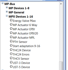
On Fupla, on the FBox selector window the FBox which supports the address range 1 to 16 are selectable from the category ‘MP-Bus’, ‘MPX Devices 1- 16’.
This means, that a PCD could handle up to 128 Belimo devices, if on all 8 possible MB-Bus lines of the PCD, only MPX devices would be connected.
MP and MPX Addressing
The 16-address feature was introduced since the library version 2.7.527
Remarks:
1.
The Duplex Driver Fbox for the PCD2.T500 module supports only the MP address range (1-8).
2.
The Single Driver Fbox supports the MP address range (1-8) as well as the MPX range (1-16) by respecting the following rules.- You can use addresses up to 16 if you have only MPX devices on the MP-Bus.
- You can mix up old MP and new MPX devices as long as all devices are in the address range 1 to 8.
- You can use 2 buses, one for the old MP devices (1-8), One for new MPX devices (1-16)
Consequently:
- If more then 8 (up to 16) devices should be connected on a MP-Bus line, then only MPX devices can be used on this the MP-Bus line.
- You cannot mix up old MP devices with new MPX devices using addresses in range 9 to 16 on the same bus.
- In other words, as long as one old MP device is on the bus the address range is limited to 1-8.
-
It’s possible to connect more than 8 MP-Bus devices on a MP-bus line (F180 or F280/F280 card)? (FAQ #102015)
Yes, it’s possible to connect up to 16 MP-Bus devices per MP-Bus line and the PCD supports the MP-Bus light protocol.
Belimo has enhanced the functionality of the MP-Bus in that way that, in some conditions, it’s possible to connect up to 16 devices on the same MP-Bus.The devices which support this feature are named MPL/MPX or/and Belimo MP-Bus light.
SBC has adapted the Belimo PG5 FBox library to support up to 16 devices per MP-Bus line.
On Fupla, on the FBox selector window the FBox which supports the address range 1 to 16 are selectable from the category ‘MP-Bus’, ‘MPX Devices 1- 16’.
This means, that a PCD could handle up to 128 Belimo devices, if on all 8 possible MB-Bus lines of the PCD, only MPX devices would be connected.
MP and MPX Addressing
The 16-address feature was introduced since the library version 2.7.527
Remarks:
1.
The Duplex Driver Fbox for the PCD2.T500 module supports only the MP address range (1-8).
2.
The Single Driver Fbox supports the MP address range (1-8) as well as the MPX range (1-16) by respecting the following rules.- You can use addresses up to 16 if you have only MPX devices on the MP-Bus.
- You can mix up old MP and new MPX devices as long as all devices are in the address range 1 to 8.
- You can use 2 buses, one for the old MP devices (1-8), One for new MPX devices (1-16)
Consequently:
- If more then 8 (up to 16) devices should be connected on a MP-Bus line, then only MPX devices can be used on this the MP-Bus line.
- You cannot mix up old MP devices with new MPX devices using addresses in range 9 to 16 on the same bus.
- In other words, as long as one old MP device is on the bus the address range is limited to 1-8.
-
Why the configuration of the DALI devices over PCD2.F2610 or PCD3.F261 and the F-Box ‘Dali Cfg Manger’ does not work correctly? (FAQ #101900)
Under certain conditions it’s possible that the configuration of the DALI devices with the F-Box ‘Dali Cfg Manger’ doesn’t work correctly.
Definition or changing of the DALI address of the DALI device, setting up the DALI parameters in the DALI device doesn’t work properly, then new values are not stored on the DALI device.
Description of the error:
Under certain conditions it’s possible that the configuration of the DALI devices with the F-Box ‘Dali Cfg Manger’ doesn’t work correctly.
Definition or changing of the DALI address of the DALI device, setting up the DALI parameters in the DALI device doesn’t work properly, then new values are not stored on the DALI device.This behavior happens, if the transmission of the configuration telegrams from the PCD to the DALI devices takes to long time.
This situation could occur if the cycle time of the application program on the PCD is to long or if the PCD does use need some cycle time for other tasks (like BACnet communication)To tests if the configuration is written correctly in to the DALI device, just read out the DALI parameters from the device after the writing of the parameters and compare this value with the previously written value.
Solution:
We have fixed the problem in that way, that we do now handle the configuration telegrams directly in the PCD2.F2610 or PCD3.F261 DALI communication module.The FW of the F2610/F261 module have to be at least the version 1.03.23.
The DALI configuration F-Box was also adapted to support the new firmware of the F2610/F261 module.
Use at least the ‘Dali-F26x’ Library version $2.7.358 or higher.Technical reason:
The DALI specification does define for the configuration telegrams which have to be send to the DALI devices, that this configuration telegram have to be send two times to the DALI device.The time delay between the first and the second configuration telegram has not to be longer then 100ms.
If the delay is > 100ms then the DALI devices does not accept the new configuration and does use the old parameters.
-
Why does my RS-232 S-Bus communication not work with the PCD2.F2xx0 and PCD3.F2xx module? (FAQ #101775)
The RS-232 S-Bus communication may doesn't work at all with PCD2.F2xx0 or PCD3.F2xx modules when communicating over converters (like modem or optical converters) to other devices. On PCD2.F2xx0 and PCD3.F2xx with Firmware less or equal V020 the handling of the RTS signal is wrong.
Symptom
Due of a Firmware error on the PCD2.F2xx0 and PCD3.F2xx module (with Firmware of the PCD2.F2xx0/PCD3.F2xx module: less or equal V020) it may be, that the S-Bus communication over converters (like modem or optical converters) to other devices does not work.
The S-Bus communication works fine, if no converters are used in between.
Also other communications protocols then S-Bus like "Mode C, Modbus" works fine on the PCD2.F2xx0 and PCD3.F2xx module (with and without converters in between).
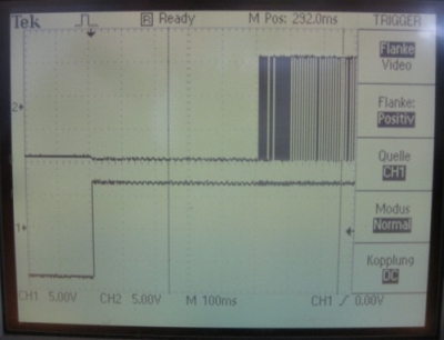
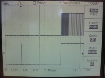
On the print screen below, the signal 1 is RTS and signal 2 is the dataflow.
With PCD3.F121, the RTS signal behaves correctly, with PCD2.F2xx0 or PCD3.F221 not.
Communication with PCD3.F121
Communication with PCD3.F221
Workaround to use the RS-232 S-Bus communication over converters:
For the PCD3:
Instead of using a PCD3.F221, use the PCD3.F121.
For PCD1.M2 or PCD2.M5:
Instead of using a PCD2.F2xx0, use the PCD7.F121S.
Solution
The Firmware version 1.xx.xx of the module PCD2.F2xx0 or PCD3.F2xx will solve this bug with the handling of the RTS signal. Please contact your local SBC Support center. -
Why do I get the error "Missing value" when reading some M-Bus devices? (FAQ #101762)
When reading values from some specific M-Bus devices with the M-Bus modules PCD2/3.F27xx, the M-Bus driver may show the error "Missing value" even though all values are correctly returned by the device.
Symptom
When using the M-Bus modules PCD2/3.F27xx (with the framing protocol), the M-Bus driver may display the error "Missing value" even though all values are correctly returned. The problem concerns only few devices; so far the following concerned devices are known:- Janitza, electricity counter
- EMU Professional, electricity counter
- L&G Ultraheat 50, heating counter
Reason
This problem occurs because the PCD firmware (older than 1.16.66) looses some bytes if the reply telegrams is longer than 240 bytes (and the framing protocol is used).
Solution
This problem is corrected in the PCD firmware version 1.16.66 and later. This firmware is e.g. contained in the BACnet firmware package available on the Support Site (under "Communication Protocols" --> "BACnet") -
Incompatibility of PCD2 /PCD3.F27x(0) and "Hydrometer M-Bus Receiver 868" (FAQ #101717)
The M-Bus communication between the "Hydrometer M-Bus Receiver 868" (alternatively called "MB-Receiver") and the PCD2.F2710 has been analyzed and it was found that the device does not conform to the M-Bus specification (SN EN 13757-2). Therefore it can not be used together with the PCD2/3.F27x(0).
During our analysis it was found that the power consumption variation of the "Hydrometer M-Bus Receiver 868" while receiving data is higher than specified in the M-Bus specification. This leads to the fact that the communication between the F271x and the "Hydrometer M-Bus Receiver 868" receiver is not working.
Note that the manufacturer is explicitly specifying that this device is only to be used with "his" M-Bus master, see screenshot below.Detailed information
Analyzed Radio Receiver: Hydrometer M-Bus Receiver 868
The device takes the power from the M-Bus communication lines; current consumption is around 20mA (instead of max. 1.5mA). So far, this is no problem as long as the device is counted as ~13x load. But when sending data on the M-Bus lines, the current consumption of this slave changes by more than 10mA, and this change is seen as incoming data on the M-Bus master side.The M-Bus standard SN EN 13757-2 specifies:
Voltage variation of 1..15V shall not change the bus current by more than Nx3uA/V. N must be specified, values in the range from 1 to 4 are allowed. Max. change with SBC M-Bus master: 12V*4*3uA/V = 144uA.
Conclusion
The "Hydrometer M-Bus Receiver 868" does not comply with M-Bus standard. (and its manufacturer specifies that this Receiver has to be used only with their master devices). Therefore it can be (by chance) that it works with third party master devices. With the F27x modules the functionality is not guaranteed (guaranteed functionality would require a hardware redesign of the F27x to support the special device).
Remark
In Germany the "Hydrometer M-Bus Receiver 868" is distributed by Hydrometer while in Switzerland it is distributed by Techem and in France the same device is distributed by the company Sappel under the name "IZAR". -
Why can't I read data from a CALEC aquametro energy master device? (FAQ #101710)
In order to read data from "CALEC aquameter energy master" devices using the F27x modules (except PCD2.F2700 or PCD3.F270) the M-Bus FBox library 2.6.117 or later is required.
Symptom
When trying to read data from a "CALEC aquametro energy master" device using e.g. a PCD3.F271 and the M-Bus FBox library (older than version 2.6.117) from Engiby a timeout is the result. This is only the case with the aquametro device, other M-Bus devices can be read correctly.
Reason
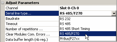
The Engiby M-Bus FBox library (older than version 2.6.117) does not read correctly from the CALEC device if the framing protocol (used for the modules PCD2.F2710 or a PCD3.F271) is configured. On the other hand data are read correctly if the character mode is configured with an F270(0) (to be selected with "RS 485/F270" as Serial line type in the M-Bus driver FBox).
Solution- Update your M-Bus library to version 2.6.117 or later (please request the library directly from Engiby)
- If it is not possible updating the FBox library it is also possible accessing the "CALEC aquametro" using a PCD3.F270 (or a PCD2.F2700) and configure it to use the character mode (see screenshot below) in the FBox "MBus Driver":
-
How to Download a Firmware to a PCD2.F2xxx or PCD3.F2xx Module (FAQ #101688)
There is a possibility to update the firmware of a PCD2.F2xxx or PCD3.F2xx, in this FAQ it is explained how to proceed.
In general the procedure is the same like you would update the firmware of a PCD3. Connect the computer via USB to the PLC and start the PG5 2.0 Firmware Downloader. Change the file for the download to the required .bin file and start the download in USB PGU mode.
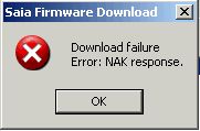
ProblemWhen more than one PCD2.F2xxx or PCD3.F2xx is plugged in the PLC there can appear some error messages.
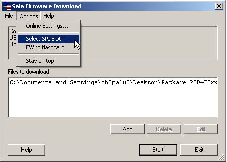
SolutionIn this case you have to specify the Slot in which the Module is plugged which you want to download the firmware into. This is made in the Options of the Firmware Downloader “Select SPI Slot…”
When choosing in which Slot you want to download the firmware you can make sure that the right module is updated, if “No Options is selected it will try to download the firmware to the first PCD2.F2xxx or PCD3.F2xx which is found on the I/O Bus.
Remark
The minimal system requirements are:
PG5 2.0.200
PCD Firmware 1.16.48
Modules supporting a firmware update:
PCD2.F26xx
PCD2.F27xx
PCD3.F26x
PCD3.F27x -
What is new in the SBC M-Bus library 2.7.006? (FAQ #101604)
In the M-Bus library for the SBC Energy Meters (which can be installed for PG5 1.4, PG5 2.0 and PG5 2.1) the following modifications have been applied.
Modification in the SBC MBus library 2.7.006 (March 2013)
- Added support for PG5 2.1
- Removed the option "BACnet"
Modification in the SBC MBus library 2.6.113 (December 2011)
- Added outputs of the FBox: total active power and total reactive power is now provided
Modification in the SBC MBus library 2.6.104 (July 2011)- A negative reactive power measured by SBC M-Bus Energy Meters was displayed incorrectly
- Support of the new modules PCD2/3.F271(0), F272(0) and F273(0)
If you use such a module, please configure the "Serial line" in the driver FBox to "M-Bus/F27xx" and ensure you have the firmware 1.16.52 or later on the PCD.
With older library version, you don’t have this option and you can only use the modules PCD2/3.F270(0) with the mode "RS485/F270".
Corrections in the SBC MBus library 2.6.014 (April 2011)- With the M-Bus library 2.6.013 the driver sent M-Bus resets repetitively
- With older versions than 2.6.014 the SBC M-Bus Energy Meters were not always correctly connected.
Remarks- There exist two libraries for M-Bus:
- The "full version" from Engiby
which supports all the M-Bus Energy meters from SBC, but also from other manufacturers
- the "SBC version"
which supports only the M-Bus Energy meters from SBC. - The "SBC version" is available from the support site;
for the "Engiby version" please contact Engiby in order to obtain the last version. www.engiby.ch - Please do install the "SBC version" or the "Engiby version" but not both in parallel; this could lead to inconsistent file combinations.
-
Why do some M-Bus devices not work on all ports of a PCD2.M5 or a PCD3? (FAQ #101382)
Some M-Bus devices (so far only observed on a MBus water counter from the company Allmess / Actris) are very sensitive against inter-character delays.
Symptom
Some M-Bus devices connected to a PCD2.F2xxx or a PCD3.F2xx (or on the ports listed below under "Remark") are not answering to all requests. The same device does work fine when the M-Bus gateway is connected to another port (e.g. on port 0 of the PCD2.M5).
Reason
The reason for this phenomenon could be that the M-Bus device is very sensitive against inter-character delays in the telegrams.
Solution
In order to avoid the inter-character delays a new feature has been implemented in the firmware of the PCD (the freeze bit, see FAQ 100916). The M-Bus library 2.5.203 from Engiby does work with this mechanism and thus avoids the inter-character delays in the telegrams.
Remark
With firmware 1.10.16 it has been observed that such inter-character delays are present in telegrams sent on the ports listed below even when using the freeze-mode mentioned:- PCD2.M5xxx: port 2 and port 3
- PCD3.Mxxxx: port 0 and port 3
In order to avoid these inter-character delays, please use firmware 1.10.51 for your PCD2.M5xx0 or PCD3. This firmware can be downloaded from the according product section on the support site www.sbc-support.ch.
-
A PCD2.W3x0 conflicts with a PCD2.F2xx0 or a PCD2.R6000 on a PCD2.M5xxx (FAQ #101262)
A hardware conflict on a PCD2.M5xxx between a PCD2.W3x0 plugged to I/O slot 3 and the modules PCD2.F2xx0 and PCD2.R6000 leads to the fact that the communication- and memory modules do not work in this constellation. If the PCD2.W3x0 is removed from the I/O slot 3 the installation is working correctly.
Symptom
In case a PCD2.W3x0 analogue input module is plugged in the I/O slot 3 (base address 48) the communication modules PCD2.F2xx0 and the memory modules PCD2.R6000 do not work.
The LEDs on a communication module PCD2.F2100, a PCD2.F2210 or a PCD2.F2810 are lit 50% red and 50% green (blinking). The file system of the PCD2.R6000 (SLxFLASH:/) are not visible over e.g. FTP. Only PCD2.M5xxx with hardware version older than C345 are concerned.
Reason
The reason for this behavior is a conflict between the PCD2.W3x0 (PCD2.W300, PCD2.W310, PCD2.W340, PCD2.W350, PCD2.W360) and the PCD2.F2xx0 or R6000. This conflict exists only if the PCD2.W3x0 is plugged on the I/O slot 3 (base address 48).
Solution- This conflict is no longer present with hardware version C345 of the PCD2.M5xxx (the according filter of the I/O bus has been adapted in order not to lead to this conflict).
- In case it is not possible to replace the system immediately (or send it to the repair service for having this modification done), the problem can be solved by not using a PCD2.W30x in the I/O slot 3. If the communication module or the memory module is plugged into I/O slot 3 the installation will work correctly.
-
Communication in Bus Terminal topology doesn't work on PCDx.F2xx Module! (FAQ #101091)
When more than 1 displays of the same type (PCD7.D23x and PCD7.D290) are connected to a RS 485 port (Bus terminal) of a PCDx.F2xx module, the communication doesn't work. Only one of the displays is available, the other one(s) is (are) not accessible!
The ports 100 to 131 available on the PCDx.F2xx modules have different timing properties and are therefore not appropriate for PCD7.D23x and PCD7.D290 in bus terminal topoloy!
Workaround:
Use another RS 485 port (onboard or with F1xx). -
Different handling of the TBSY flag (in MC mode) between PCD3 / PCD2.M5 and older systems (FAQ #100655)
The diagnostic flag TBSY of the "Character Mode" (used for sending characters over a serial line) is not handled the same way on a PCD3 compared to "older" systems like e.g. PCD2.M170.
Symptom
If the relevant port is assigned in MC mode, the diagnostic flag TBSY is indicating that the serial port is busy sending characters. This is the case on e.g. a PCD2.M170.
This behaviour is not the same on a PCD2.M5xxx or a PCD3.Mxxxx, especially not when using a PCD3.F121 or a F2xx(x) modules. On a PCD3/PCD2.M5 the TBSY flag is not any more high during the whole time the port is busy. Instead, it is only high a short time at the very beginning of the send task.Reason
The reason for this difference is a new manner to access the UART of the port. On older systems the characters were directly written to the UART while on the PCD3 a buffer is placed in-between. Instead of indicating the "send-state" of the UART like on older systems, the TBSY represents the state of this buffer (the size can be found at the end of this FAQ) on the PCD3 or the PCD2.M5.Solution
This difference shouldn't lead to problem is most cases. However, in some applications the state of the TBSY is used to control e.g. the RTS signal of the line (using the instruction SOCL). In this case the communication (working on a PCD2.M170) won't work any more on a PCD3 or a PCD2.M5.
In this situation one of the following workarounds could be applied:- Instead of assigning the port in MC0 it could be assigned in MC4 (MC4 is usually described as "MC for RS485"). In this mode the UART is managing the RTS autonomously (and therefore there is no more need to set the RTS by the user program). Note that in this case the SOCL commands are to be removed from the program!
- The duration while the RTS is to be set could be calculated beforehand (based on the amount of characters to be sent) and loaded into a timer. While this timer is high, the RTS can be set using the SOCL command.
Note that this solution is not really a "nice" one and can only work with very low baud rates.
Notes
- All firmware versions of the PCD3xxx and PCD2.M5xxx do treat the TBSY as described in this FAQ.
- The buffer size is depending on the port used:
PCD3 port 1 and 2: 24 characters
PCD3 port 0 and 3: 2 characters
PCD2.M5 port 0 and 1: 24 characters
PCD2.M5 port 2 and 3: 2 characters
PCD3 / Fxxx
-
Are the LonWorks devices PCD2.F240, PCD3.F2400 and PCD7.R582 still available? (FAQ #102064)
No, the LonWorks devices PCD2.F240, PCD3.F2400 and PCD7.R582 are no longer available.
The production of the LonWorks interface devices PCD2.F240, PCD3.F2400 and the LonWorks memory device PCD7.R582 was discontinued at the end of 2021 and the devices are no longer available.
As a replacement, we recommend the usage of BACnet.
-
Why are the inputs and outputs of a PCD3 systems not switched on and off correctly, or switched on and off randomly, or the I/O status not detected correctly in the PLC? (FAQ #102063)
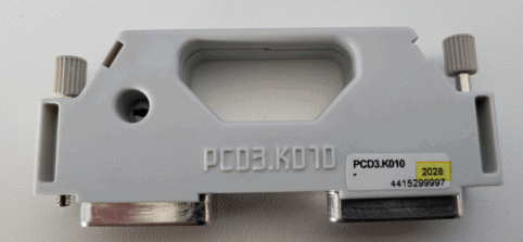
The problem may be related to a loose contact on the PCD3.K010 connectors used to connect the PCD3.M/Txxx CPU's and the PCD3.Cxxx expansion modules.
In this case, various error patterns may occur, such as
- - If an input is set to 1, then several inputs are set to 1 at the same time.
- - If an output is set to 1 in the application program, then the output is not set on the output module.
- - The status of the inputs is not correctly recognised in the application program.
The affected PCD3.K010 modules have a manufacturing date of 2028 (year 2020, week 28).
If the symptoms described above occur and a PCD3.K010 module with fabrication date 2028 is used, replace the PCD3.K010 module with a new PCD3.K010 module.
Order new PCD3.K010 modules and create an RMA request with the error description and the remark: CRABBMS-430 and select the option 'Advanced replacement'.
The date of manufacture can be seen on the white sticker on the PCD3.K010.
-
Does the PCD support the MP-Bus light protocol and it’s possible connect up to 16 Belimo devices to one MP-Bus line? (FAQ #102016)
Yes, it’s possible to connect up to 16 MP-Bus devices per MP-Bus line and the PCD supports the MP-Bus light protocol.
Belimo has enhanced the functionality of the MP-Bus in that way that, in some conditions, it’s possible to connect up to 16 devices on the same MP-Bus.The devices which support this feature are named MPL/MPX or/and Belimo MP-Bus light.
SBC has adapted their Belimo PG5 FBox library to support up to 16 devices per MP-Bus line.
On Fupla, on the FBox selector window the FBox which supports the address range 1 to 16 are selectable from the category ‘MP-Bus’, ‘MPX Devices 1- 16’.
This means, that a PCD could handle up to 128 Belimo devices, if on all 8 possible MB-Bus lines of the PCD, only MPX devices would be connected.
MP and MPX Addressing
The 16-address feature was introduced since the library version 2.7.527
Remarks:
1.
The Duplex Driver Fbox for the PCD2.T500 module supports only the MP address range (1-8).
2.
The Single Driver Fbox supports the MP address range (1-8) as well as the MPX range (1-16) by respecting the following rules.- You can use addresses up to 16 if you have only MPX devices on the MP-Bus.
- You can mix up old MP and new MPX devices as long as all devices are in the address range 1 to 8.
- You can use 2 buses, one for the old MP devices (1-8), One for new MPX devices (1-16)
Consequently:
- If more then 8 (up to 16) devices should be connected on a MP-Bus line, then only MPX devices can be used on this the MP-Bus line.
- You cannot mix up old MP devices with new MPX devices using addresses in range 9 to 16 on the same bus.
- In other words, as long as one old MP device is on the bus the address range is limited to 1-8.
-
It’s possible to connect more than 8 MP-Bus devices on a MP-bus line (F180 or F280/F280 card)? (FAQ #102015)
Yes, it’s possible to connect up to 16 MP-Bus devices per MP-Bus line and the PCD supports the MP-Bus light protocol.
Belimo has enhanced the functionality of the MP-Bus in that way that, in some conditions, it’s possible to connect up to 16 devices on the same MP-Bus.The devices which support this feature are named MPL/MPX or/and Belimo MP-Bus light.
SBC has adapted the Belimo PG5 FBox library to support up to 16 devices per MP-Bus line.
On Fupla, on the FBox selector window the FBox which supports the address range 1 to 16 are selectable from the category ‘MP-Bus’, ‘MPX Devices 1- 16’.
This means, that a PCD could handle up to 128 Belimo devices, if on all 8 possible MB-Bus lines of the PCD, only MPX devices would be connected.
MP and MPX Addressing
The 16-address feature was introduced since the library version 2.7.527
Remarks:
1.
The Duplex Driver Fbox for the PCD2.T500 module supports only the MP address range (1-8).
2.
The Single Driver Fbox supports the MP address range (1-8) as well as the MPX range (1-16) by respecting the following rules.- You can use addresses up to 16 if you have only MPX devices on the MP-Bus.
- You can mix up old MP and new MPX devices as long as all devices are in the address range 1 to 8.
- You can use 2 buses, one for the old MP devices (1-8), One for new MPX devices (1-16)
Consequently:
- If more then 8 (up to 16) devices should be connected on a MP-Bus line, then only MPX devices can be used on this the MP-Bus line.
- You cannot mix up old MP devices with new MPX devices using addresses in range 9 to 16 on the same bus.
- In other words, as long as one old MP device is on the bus the address range is limited to 1-8.
-
Why the configuration of the DALI devices over PCD2.F2610 or PCD3.F261 and the F-Box ‘Dali Cfg Manger’ does not work correctly? (FAQ #101900)
Under certain conditions it’s possible that the configuration of the DALI devices with the F-Box ‘Dali Cfg Manger’ doesn’t work correctly.
Definition or changing of the DALI address of the DALI device, setting up the DALI parameters in the DALI device doesn’t work properly, then new values are not stored on the DALI device.
Description of the error:
Under certain conditions it’s possible that the configuration of the DALI devices with the F-Box ‘Dali Cfg Manger’ doesn’t work correctly.
Definition or changing of the DALI address of the DALI device, setting up the DALI parameters in the DALI device doesn’t work properly, then new values are not stored on the DALI device.This behavior happens, if the transmission of the configuration telegrams from the PCD to the DALI devices takes to long time.
This situation could occur if the cycle time of the application program on the PCD is to long or if the PCD does use need some cycle time for other tasks (like BACnet communication)To tests if the configuration is written correctly in to the DALI device, just read out the DALI parameters from the device after the writing of the parameters and compare this value with the previously written value.
Solution:
We have fixed the problem in that way, that we do now handle the configuration telegrams directly in the PCD2.F2610 or PCD3.F261 DALI communication module.The FW of the F2610/F261 module have to be at least the version 1.03.23.
The DALI configuration F-Box was also adapted to support the new firmware of the F2610/F261 module.
Use at least the ‘Dali-F26x’ Library version $2.7.358 or higher.Technical reason:
The DALI specification does define for the configuration telegrams which have to be send to the DALI devices, that this configuration telegram have to be send two times to the DALI device.The time delay between the first and the second configuration telegram has not to be longer then 100ms.
If the delay is > 100ms then the DALI devices does not accept the new configuration and does use the old parameters.
-
PCD3.F27x and PCD2.F27xx M-Bus is not always short cut protected! (FAQ #101870)
Those M-Bus cards have a short-cut protection on the bus but when the CPU isn't anymore power supplied and the F27x(x) card still has 24 V supply there is no short cut protection anymore!
Reason:
The 36 Volts from the M-Bus will destroy some components on the concerned serial port of the card!
Solution:
Use the same power supply for the CPU as for the PCDx.F27x(x) card or if for some reason a different power supply has to be used be aware that in case the CPU isn't power supplied that the M-Bus is NOT short-circuited!
-
Why does my RS-232 S-Bus communication not work with the PCD2.F2xx0 and PCD3.F2xx module? (FAQ #101775)
The RS-232 S-Bus communication may doesn't work at all with PCD2.F2xx0 or PCD3.F2xx modules when communicating over converters (like modem or optical converters) to other devices. On PCD2.F2xx0 and PCD3.F2xx with Firmware less or equal V020 the handling of the RTS signal is wrong.
Symptom
Due of a Firmware error on the PCD2.F2xx0 and PCD3.F2xx module (with Firmware of the PCD2.F2xx0/PCD3.F2xx module: less or equal V020) it may be, that the S-Bus communication over converters (like modem or optical converters) to other devices does not work.
The S-Bus communication works fine, if no converters are used in between.
Also other communications protocols then S-Bus like "Mode C, Modbus" works fine on the PCD2.F2xx0 and PCD3.F2xx module (with and without converters in between).
On the print screen below, the signal 1 is RTS and signal 2 is the dataflow.
With PCD3.F121, the RTS signal behaves correctly, with PCD2.F2xx0 or PCD3.F221 not.
Communication with PCD3.F121
Communication with PCD3.F221
Workaround to use the RS-232 S-Bus communication over converters:
For the PCD3:
Instead of using a PCD3.F221, use the PCD3.F121.
For PCD1.M2 or PCD2.M5:
Instead of using a PCD2.F2xx0, use the PCD7.F121S.
Solution
The Firmware version 1.xx.xx of the module PCD2.F2xx0 or PCD3.F2xx will solve this bug with the handling of the RTS signal. Please contact your local SBC Support center. -
Why do I get the error "Missing value" when reading some M-Bus devices? (FAQ #101762)
When reading values from some specific M-Bus devices with the M-Bus modules PCD2/3.F27xx, the M-Bus driver may show the error "Missing value" even though all values are correctly returned by the device.
Symptom
When using the M-Bus modules PCD2/3.F27xx (with the framing protocol), the M-Bus driver may display the error "Missing value" even though all values are correctly returned. The problem concerns only few devices; so far the following concerned devices are known:- Janitza, electricity counter
- EMU Professional, electricity counter
- L&G Ultraheat 50, heating counter
Reason
This problem occurs because the PCD firmware (older than 1.16.66) looses some bytes if the reply telegrams is longer than 240 bytes (and the framing protocol is used).
Solution
This problem is corrected in the PCD firmware version 1.16.66 and later. This firmware is e.g. contained in the BACnet firmware package available on the Support Site (under "Communication Protocols" --> "BACnet") -
Incompatibility of PCD2 /PCD3.F27x(0) and "Hydrometer M-Bus Receiver 868" (FAQ #101717)
The M-Bus communication between the "Hydrometer M-Bus Receiver 868" (alternatively called "MB-Receiver") and the PCD2.F2710 has been analyzed and it was found that the device does not conform to the M-Bus specification (SN EN 13757-2). Therefore it can not be used together with the PCD2/3.F27x(0).
During our analysis it was found that the power consumption variation of the "Hydrometer M-Bus Receiver 868" while receiving data is higher than specified in the M-Bus specification. This leads to the fact that the communication between the F271x and the "Hydrometer M-Bus Receiver 868" receiver is not working.
Note that the manufacturer is explicitly specifying that this device is only to be used with "his" M-Bus master, see screenshot below.Detailed information
Analyzed Radio Receiver: Hydrometer M-Bus Receiver 868
The device takes the power from the M-Bus communication lines; current consumption is around 20mA (instead of max. 1.5mA). So far, this is no problem as long as the device is counted as ~13x load. But when sending data on the M-Bus lines, the current consumption of this slave changes by more than 10mA, and this change is seen as incoming data on the M-Bus master side.The M-Bus standard SN EN 13757-2 specifies:
Voltage variation of 1..15V shall not change the bus current by more than Nx3uA/V. N must be specified, values in the range from 1 to 4 are allowed. Max. change with SBC M-Bus master: 12V*4*3uA/V = 144uA.
Conclusion
The "Hydrometer M-Bus Receiver 868" does not comply with M-Bus standard. (and its manufacturer specifies that this Receiver has to be used only with their master devices). Therefore it can be (by chance) that it works with third party master devices. With the F27x modules the functionality is not guaranteed (guaranteed functionality would require a hardware redesign of the F27x to support the special device).
Remark
In Germany the "Hydrometer M-Bus Receiver 868" is distributed by Hydrometer while in Switzerland it is distributed by Techem and in France the same device is distributed by the company Sappel under the name "IZAR". -
Why can't I read data from a CALEC aquametro energy master device? (FAQ #101710)
In order to read data from "CALEC aquameter energy master" devices using the F27x modules (except PCD2.F2700 or PCD3.F270) the M-Bus FBox library 2.6.117 or later is required.
Symptom
When trying to read data from a "CALEC aquametro energy master" device using e.g. a PCD3.F271 and the M-Bus FBox library (older than version 2.6.117) from Engiby a timeout is the result. This is only the case with the aquametro device, other M-Bus devices can be read correctly.
Reason
The Engiby M-Bus FBox library (older than version 2.6.117) does not read correctly from the CALEC device if the framing protocol (used for the modules PCD2.F2710 or a PCD3.F271) is configured. On the other hand data are read correctly if the character mode is configured with an F270(0) (to be selected with "RS 485/F270" as Serial line type in the M-Bus driver FBox).
Solution- Update your M-Bus library to version 2.6.117 or later (please request the library directly from Engiby)
- If it is not possible updating the FBox library it is also possible accessing the "CALEC aquametro" using a PCD3.F270 (or a PCD2.F2700) and configure it to use the character mode (see screenshot below) in the FBox "MBus Driver":
-
How to Download a Firmware to a PCD2.F2xxx or PCD3.F2xx Module (FAQ #101688)
There is a possibility to update the firmware of a PCD2.F2xxx or PCD3.F2xx, in this FAQ it is explained how to proceed.
In general the procedure is the same like you would update the firmware of a PCD3. Connect the computer via USB to the PLC and start the PG5 2.0 Firmware Downloader. Change the file for the download to the required .bin file and start the download in USB PGU mode.
ProblemWhen more than one PCD2.F2xxx or PCD3.F2xx is plugged in the PLC there can appear some error messages.
SolutionIn this case you have to specify the Slot in which the Module is plugged which you want to download the firmware into. This is made in the Options of the Firmware Downloader “Select SPI Slot…”
When choosing in which Slot you want to download the firmware you can make sure that the right module is updated, if “No Options is selected it will try to download the firmware to the first PCD2.F2xxx or PCD3.F2xx which is found on the I/O Bus.
Remark
The minimal system requirements are:
PG5 2.0.200
PCD Firmware 1.16.48
Modules supporting a firmware update:
PCD2.F26xx
PCD2.F27xx
PCD3.F26x
PCD3.F27x -
What is new in the SBC M-Bus library 2.7.006? (FAQ #101604)
In the M-Bus library for the SBC Energy Meters (which can be installed for PG5 1.4, PG5 2.0 and PG5 2.1) the following modifications have been applied.
Modification in the SBC MBus library 2.7.006 (March 2013)
- Added support for PG5 2.1
- Removed the option "BACnet"
Modification in the SBC MBus library 2.6.113 (December 2011)
- Added outputs of the FBox: total active power and total reactive power is now provided
Modification in the SBC MBus library 2.6.104 (July 2011)- A negative reactive power measured by SBC M-Bus Energy Meters was displayed incorrectly
- Support of the new modules PCD2/3.F271(0), F272(0) and F273(0)
If you use such a module, please configure the "Serial line" in the driver FBox to "M-Bus/F27xx" and ensure you have the firmware 1.16.52 or later on the PCD.
With older library version, you don’t have this option and you can only use the modules PCD2/3.F270(0) with the mode "RS485/F270".
Corrections in the SBC MBus library 2.6.014 (April 2011)- With the M-Bus library 2.6.013 the driver sent M-Bus resets repetitively
- With older versions than 2.6.014 the SBC M-Bus Energy Meters were not always correctly connected.
Remarks- There exist two libraries for M-Bus:
- The "full version" from Engiby
which supports all the M-Bus Energy meters from SBC, but also from other manufacturers
- the "SBC version"
which supports only the M-Bus Energy meters from SBC. - The "SBC version" is available from the support site;
for the "Engiby version" please contact Engiby in order to obtain the last version. www.engiby.ch - Please do install the "SBC version" or the "Engiby version" but not both in parallel; this could lead to inconsistent file combinations.
-
Why do some M-Bus devices not work on all ports of a PCD2.M5 or a PCD3? (FAQ #101382)
Some M-Bus devices (so far only observed on a MBus water counter from the company Allmess / Actris) are very sensitive against inter-character delays.
Symptom
Some M-Bus devices connected to a PCD2.F2xxx or a PCD3.F2xx (or on the ports listed below under "Remark") are not answering to all requests. The same device does work fine when the M-Bus gateway is connected to another port (e.g. on port 0 of the PCD2.M5).
Reason
The reason for this phenomenon could be that the M-Bus device is very sensitive against inter-character delays in the telegrams.
Solution
In order to avoid the inter-character delays a new feature has been implemented in the firmware of the PCD (the freeze bit, see FAQ 100916). The M-Bus library 2.5.203 from Engiby does work with this mechanism and thus avoids the inter-character delays in the telegrams.
Remark
With firmware 1.10.16 it has been observed that such inter-character delays are present in telegrams sent on the ports listed below even when using the freeze-mode mentioned:- PCD2.M5xxx: port 2 and port 3
- PCD3.Mxxxx: port 0 and port 3
In order to avoid these inter-character delays, please use firmware 1.10.51 for your PCD2.M5xx0 or PCD3. This firmware can be downloaded from the according product section on the support site www.sbc-support.ch.
-
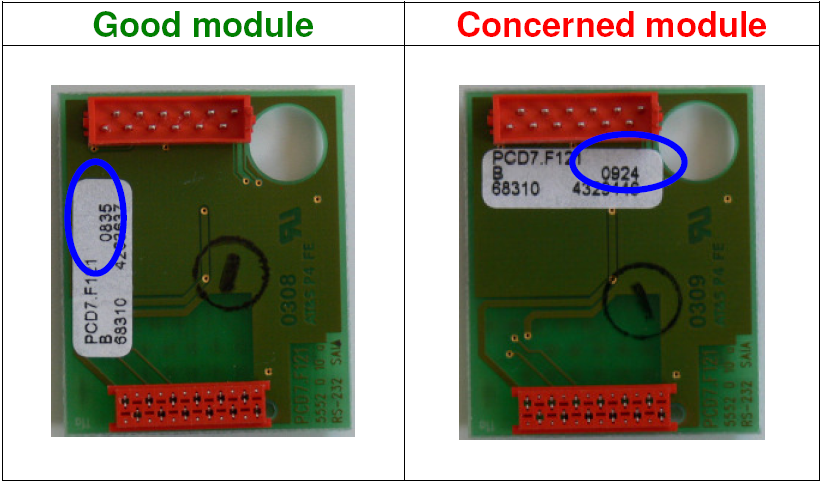
Incompatibility of PCD7.F121 with PCD2.F2xxx / PCD3.F2xx (FAQ #101380)
Due to the different electric properties of the RS232 driver mounted on the PCD7.F121 produced between June 2009 and September 10 2009, these modules do not work at all or not correctly when mounted on a PCD2.F2xxx or a PCD3.F2xx.
The reason for the different electrical properties is that the driver is delivered by a new manufacturer. We did not notice this malfunction in our production because the F2xx modules are delivered separately from the PCD7.F1xx modules, as they are mounted afterwards by the customer.
Identification of concerned PCD7.F121
PCD7.F121 applied on PCD2.F2xxx and PCD3.F2xx which were delivered between June and 10th of September 2009 (production date 0923 to 0936). These modules are equipped with ICs from manufacturer Sipex and have hardware version B without modification 1.
Not concerned products
• Any PCD7.F121 not applied in PCD2.F2xxx or PCD3.F2xx
• PCD7.F121 with production date before 0923 (generally equipped with an IC from the manufacturer Max)
• PCD7.F121 delivered after 10th of September2009, equipped with IC from Max or Sipex but with version B1
If you have concernde moduls, contact your local representation to exchange them. -
Is Modbus supported by Saia PCD®s? (FAQ #101270)
Yes, Modbus is supported by the firmware of recent Saia PCD® systems (on all ports, including the ones on F2xx modules since beginning of 2011) or by a dedicated FBox driver.
General
There are two possibilities to use Modbus on SBC CPUs (Classic versions).- The new FBox library for Modbus "Modbus SBC Version" which takes advantage of the Modbus implementation directly in the Saia PCD® COSinus firmware.
Available for PCD1.M2, PCD3 and PCD2.M5 with firmware version 1.10.16 or more recent (for using on F2xx modules, in minimum FW 1.14.23 is required). - The Modbus FBox Library from our partner ENGIBY which is available since several years (www.engiby.ch) and supported also by PCD systems previous to the PCD3, PCD2.M5xxx and PCD1.M2xxx families (e.g. PCD2.M1x0, PCD2.M480 or PCD1.M1xx).
Remarks
- In order to use the firmware implementation of Modbus on PCD2.F2xxx or PCD3.F2xx modules, the following prerequisites need to be fullfilled:
- minimal PCD firmware: 1.14.25 (1.14.23 does support the F2xx modules, but
communication errors can occur)
- minimal hardware version of the F2xx(x) module: version D (delivered since beginning 2011) - The FBoxes for "Modbus SBC Version" are available for download from the support site since July 2009.
In PG5 2.0.110 and later the "Modbus SBC Version" is installed by default. Please note that a licence is required for this library.
- The new FBox library for Modbus "Modbus SBC Version" which takes advantage of the Modbus implementation directly in the Saia PCD® COSinus firmware.
-
Communication in Bus Terminal topology doesn't work on PCDx.F2xx Module! (FAQ #101091)
When more than 1 displays of the same type (PCD7.D23x and PCD7.D290) are connected to a RS 485 port (Bus terminal) of a PCDx.F2xx module, the communication doesn't work. Only one of the displays is available, the other one(s) is (are) not accessible!
The ports 100 to 131 available on the PCDx.F2xx modules have different timing properties and are therefore not appropriate for PCD7.D23x and PCD7.D290 in bus terminal topoloy!
Workaround:
Use another RS 485 port (onboard or with F1xx). -
Why does the communication on the PCD3.F281 not work? (FAQ #101090)
If the communication on both ports of a PCD3.F281 does not work then it's possible that the PCD3 does contain a FW which not does recognise the PCD3.F281 module.
Symptom
The communication on both ports of the PCD3.F281 does not work at all. The firmware installed is 1.08.23.
Reason
The firmware does not recognize the Belimo MP Bus module.
Solution
To solve the problem please install PCD3 firmware version 1.10.16 (the first firmware solving the problem was version 1.08.51). -
Where can I plug flash memory modules on a PCD3 CPU? (FAQ #101027)
There are various possibilities to plug flash memory modules (PCD7.R500, PCD7.R550M04, PCD7.R551M04, PCD7.R560 and PCD7.R561) on the CPUs.
It’s possible to plug the PCD7.R500, PCD7.R550M04, PCD7.R551M04, PCD7.R560 and PCD7.R561 modules in the following slots:
- M1 and M2 of the PCD3.M5/6 CPUs
- Memory module holder PCD3.R550 in the slots 0 to 3 of the PCD3.Mxx0 CPUs
- Memory module holder PCD3.R560 in the slots 0 to 3 of the PCD3.Mxx0 CPUs
- Communication module PCD3.F1xx only in the slot 0 of the PCD3.Mxx0 CPU's
The "backup user program" functionality does work on any of the above mentioned slots if the module PCD7.R500, PCD7.F551M04 or PCD7.R561 are used.
-
Why does my S-Bus communication with an PCD3.F2xx module show a diagnostic error? (FAQ #101011)
The Sasi S-Bus Master F-Box indicates a diagnostic error and is red. The data is transmitted but obviously not properly.
Problem
The S-Bus communication is not working properly if the baudrate is 9600 baud or higher and a PCD3.F2xx module is involved in this communication. With a baudrate 4800 it works well.
Reason
The PCD3.F2xx module is not as fast as a "normal" S-Bus port like per example Port 2 on the PCD3. If there is an S-Bus communication running with e.g an PCD3.F2xx as master and a PCD3.Mxxx port 2 as slave, the communication will probably report diagnostic errors with baudrates higher than 4800.
If the PCD3.F2xx module is the slave, it is less critical but can lead to problems as well.
Solution
To avoid this problem the turnaround delay TN of the other station (not the one where the PCD3.F2xx is plugged) has to be set to 3ms. -
Is it possible to have more than one MP-Bus master in a Fupla File? (FAQ #100958)
It was not possible before the MP-Bus library 2.5.300 which was distributed with PG5 1.4.300.
Problem
Since the new PCD3.F2xx modules where developped it was possible to have up to 8 MP-Bus Masters in a project. With the old MP-Bus Belimo library it was not possible to have more than one master in a Fupla file.
Solution
With the new MP-Bus library >=2.5.300 it is now possible to have several MP-Bus Masters in one project. The master now have a name "Channel" and the differnet F-Boxes refer to this "Channel".
Restriction
If an old project is converted to the Belimo MP Bus Version 2.5.300 / 2.5.301 it could be, that compiling is not possible anymore due to a conflict. In this case install the version 2.5.302 or higher (FAQ 100 957). -
Why is it no more possible to build an old Belimo MP-Bus project with PG5 1.4.300? (FAQ #100957)
There are error messages displayed for each old FBox that it should be replaced.
Problem
After installing the new version of the Belimo library which allows to have more than one MP-Bus Master in a Fupla file, it is not possible anymore to build the old projects.
Reason
The MP-Bus Belimo library 2.5.300 and 2.5.301 had an incompatibility with older MP-Bus Versions. The library 2.5.300 was distributed with PG5 1.4.300.
Solution
Please update your MP-Bus FBox library version to version 2.5.302 or higher. The latest version of the FBox library can be downloaded from the support site in the section "Product information" --> "Software" --> "PG5" --> "FBox libraries". -
Supported PCD communication ports for EIB/KNX driver (FAQ #100792)
For BCU1 protocol not all communication interfaces of a PCD3 or a PCD2.M5540 can be used. On the other hand there is no problem using the newer FT1.2 protocol which is supported by all RS232 interfaces of the PCD3 and the PCD2.M5540.
Supported communication interfaces for EIB/KNX driver
The table below shows the supported communication interfaces for connecting an EIB coupler to PCD3-, PCD2.M5540 and PCD1.M2120 systems. On other systems (e.g. PCD2.M170) all RS232 interfaces can be used for connecting an EIB/KNX coupler.CPU type PCD3.M5/6xx0 - PCD2.M5540 PCD3.Mxxx0 PCD3.Mxxx0 PCD2.M5540PCD1.M2120 Communication interface PGU port (onboard)PCD3.F121PCD3.F2xxPCD7.F121sPCD7.F121s BCU1 okoknot supportednot supportedt.b.c FT1.2 okokokokt.b.c
Remark
We strongly recommend using FT1.2 (also known as BCU2) for new projects as this implementation is more performant (due to a higher baudrate supported and telegram oriented transmission control rather than character-oriented transmission control which is used by BCU1). The table above represent functional tests; there is no relation to the communication performance. -
Callback of PCD7.R500 module (FAQ #100783)
Two series of PCD7.R500 which where produced in 2007 do contain a wrong configuration information on the EEPROM of the PCD7.R500.
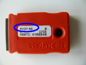
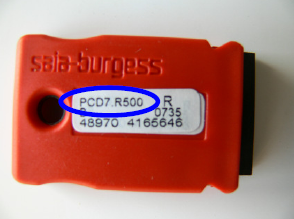
The series can be identified easily by the article name "PCD7.R5" (written on the white label on the module) and fabrication date 0727 or 0735.
Saia-Burgess Controls AG has delivered two series of PCD7.R500 modules which do contain wrong configuration information in the EEPROM of the PCD7.R500.This wrong configuration information can lead to malfunction of the file system access of the PCD3 and on the communication module of the PCD3.
Behaviour of the malfunction
The program backup functionality of the bad PCD7.R500 does work correctly.
If the PCD7.R500 module is placed together with a PCD7.R5xx, PCD3.R5xx, PCD3.F1xx or PCD3.F2xx module on the slots M1, M2 or the I/O card slots 0 to 3 of the PCD3, then the file system of the PCD3.R5xx or PCD7.R5xx is no more accessible from any external device (e.g. a Web-Panel) neither from the application program. Also the communication ports of the PCD3.F1xx or PCD3.F2xx on the I/O card slots 0 to 3 don’t work at all.
Remark about the malfunction: All PCD7.R5xx and PCD3.R5xx which are plugged on the right side of a bad PCD7.R500 are concerned by the malfunction. This means that if a bad PCD7.R500 is plugged in slot M1, then the file system on the PCD7.R5xx (plugged on the slot M2 or in I/O card slots 0 to 3) is not accessible. If the PCD7.R5xx is placed on the left side (slot M1) of a bad PCD7.R500 (slot M2), then the PCD7.R5xx on the Slot M1 does work properly.
Concerned PCD7.R500 modules
All PCD7.R500 modules with article name “PCD7.R5” (written on the white label on the PCD7.R500) and fabrication date 0727 or 0735 are concerned.Bad module Good module Corrective measure
Saia-Burgess Controls AG has reprogrammed all PCD7.R500 on stock in Murten with a correct configuration. All correctly programmed modules do have the article name “PCD7.R500” on the white label of the PCD7.R500 module.
In case you have received a PCD7.R500 module affected the above desribed wrong configuration, please contact your local Saia-Burgess Controls AG representative. -
Why are all MP-Bus FBoxes green but all values are zero? (FAQ #100744)
There is a problem in the Belimo library distributed togehter with PG5 1.4.200.
Symptom
All MP-Bus F-Boxes are green but no values are beeing transmitted.Reason
There is a problem in the Belimo library 2.5.140 which is installed together PG5 1.4.200
Solution
A correction for this problem has been implemented in the MP Bus library version 2.5.142. The easyest way for resolving the problem is updating to PG5 1.4.300 or higher (the latest PG5 version is available on the supportsite www.sbc-support.ch in the section "Product info" --> "Software" --> "PG5"). -
Can I use the character mode with XON/XOFF protocol on NT-PCD's? (FAQ #100700)
Depending of the PCD type and the used port it's possible to use the XON/XOFF protocol.
Symptom
A SASI (Assign Serial Interface) in mode MC2 (Character mode with Xon/Xoff protocol) fails. The error flag is set after the SASI instruction.
Reason
The XON/XOFF protocol is not supported on this PCD or port.
List of supported ports
PCD3.M5xxx: the mode MC2 is supported on port 0 (Com/PGU) and also on the PCD3M5340 in RS422 on port 3 (S-Net/MPI).
PCD2.M5xxx: the mode MC2 is supported on port 2.
PCD1.M2xxx: the mode MC2 is not supported.
Remark
Please note that on the PCD2/3.F2xx modules, the XON/XOFF mode is not yet supported (which is not correctly documented in the manual 26/789). -
Why does my PCD3.F180 stop communicating after a certain time? (FAQ #100693)
In some cases it can happen that the PCD3.F180 (produced between 2006 and Febrauary 2007) works well for a certain time but suddenly stops communicating. This behaviour is related to the hardware version of the PCD3.F180.
Symptom
The PCD3.F180 (produced between 2006 and Febrauary 2007) works well for a certain time but suddenly stops communicating. In some cases it is also possible that it doesn't work at all.Reason
The base print of the PCD3.F180 was designed in a way that the ground signal was not properly stabilized. This problem has been corrected in February 2007.Solution
As solution a bridge between the PGND and the GND terminals of the PCD3.F180 can be installed. Therefore please connect the pin 0 with pin 4 on the terminals on the front of the module.Remark
Modules produced after February 2007 are not concerned by the problem explained in this FAQ and therefore no additional bridge is required. -
Different handling of the TBSY flag (in MC mode) between PCD3 / PCD2.M5 and older systems (FAQ #100655)
The diagnostic flag TBSY of the "Character Mode" (used for sending characters over a serial line) is not handled the same way on a PCD3 compared to "older" systems like e.g. PCD2.M170.
Symptom
If the relevant port is assigned in MC mode, the diagnostic flag TBSY is indicating that the serial port is busy sending characters. This is the case on e.g. a PCD2.M170.
This behaviour is not the same on a PCD2.M5xxx or a PCD3.Mxxxx, especially not when using a PCD3.F121 or a F2xx(x) modules. On a PCD3/PCD2.M5 the TBSY flag is not any more high during the whole time the port is busy. Instead, it is only high a short time at the very beginning of the send task.Reason
The reason for this difference is a new manner to access the UART of the port. On older systems the characters were directly written to the UART while on the PCD3 a buffer is placed in-between. Instead of indicating the "send-state" of the UART like on older systems, the TBSY represents the state of this buffer (the size can be found at the end of this FAQ) on the PCD3 or the PCD2.M5.Solution
This difference shouldn't lead to problem is most cases. However, in some applications the state of the TBSY is used to control e.g. the RTS signal of the line (using the instruction SOCL). In this case the communication (working on a PCD2.M170) won't work any more on a PCD3 or a PCD2.M5.
In this situation one of the following workarounds could be applied:- Instead of assigning the port in MC0 it could be assigned in MC4 (MC4 is usually described as "MC for RS485"). In this mode the UART is managing the RTS autonomously (and therefore there is no more need to set the RTS by the user program). Note that in this case the SOCL commands are to be removed from the program!
- The duration while the RTS is to be set could be calculated beforehand (based on the amount of characters to be sent) and loaded into a timer. While this timer is high, the RTS can be set using the SOCL command.
Note that this solution is not really a "nice" one and can only work with very low baud rates.
Notes
- All firmware versions of the PCD3xxx and PCD2.M5xxx do treat the TBSY as described in this FAQ.
- The buffer size is depending on the port used:
PCD3 port 1 and 2: 24 characters
PCD3 port 0 and 3: 2 characters
PCD2.M5 port 0 and 1: 24 characters
PCD2.M5 port 2 and 3: 2 characters
-
Possible reasons for not working PCD3.F1xx (FAQ #100649)
In case a PCD3.F1xx module doesn't work several reasons are possible. This FAQ supplies a summary of these possible reasons.
Symptom
The communication on port 1 of the PCD3 does not work. In case the port is configured as PGU port (e.g as modem port or as serial PGU port) the PCD does not even go in run and shows a history entry ("Modem Port init fail" or "PGU port init fail").
If the port is not used as PGU port, the error led will be lit during startup of the PCD3.Possible reasons
- The PCD3.F121 is defective or incorrecty wired.
- The port has been assigned with a "Sasi Slave" FBox and the interface has been spedified as RS232
Refer to FAQ 100420 for further information. - On the same PCD3 another intelligent module (e.g. a PCD3.Rxxx) is mounted.
Refer to FAQ 100636 for further information. - The hardware version of the PCD3 is <D and more than two PCD3.Cxxx are connected to the PCD.
Refer to FAQ 100549 for further information. - The module is a "pilot module" (delivered during the pilot phase of the PCD3.F1xx modules) and is not correcty programmed. In this case the module identification is missing and the module needs to be replaced.
- A PCD7.F120 is mounted on the PCD3.F121
Refer to FAQ 100646 for further information.
- The PCD3.F121 is defective or incorrecty wired.
-
Why does a PCD7.F120 not work when used on a PCD3 or a PCD2.M5? (FAQ #100646)
When mounting a PCD7.F120 into a PCD3.F121 / PCD3.F2xx or when using a PCD7.F120 on a PCD2.M5, the communication doesn't work. The reason therefore is an incompatibility between the PCD7.F120 and PCD3.Fxxx (or PCD2.M5) modules and the old .
Symptom
After having mounted a PCD7.F120 into a PCD3.Fxxx or on a PCD2.M5, the communication doesn't work. No communication is possible using the relevant port.Reason
The PCD7.F120 does require a power supply which is not present on the PCD3.Fxxx modules or on the sockets from PCD2.M5xxx / PCD2.M48x CPUs. This power supply is not present because the new communication module PCD7.F121 (which supports baud rates up to 115 kBit/s) doesn't require a power supply any more.Solution
In case you are concerned by this problem just replace the PCD7.F120 by a PCD7.F121.Remark
All modules PCD3.Fxxx ordered as RS232 module are delivered together with a PCD7.F121 (In fact, the PCD7.F120 has been replaced by the PCD7.F121). The only situation where a problem can occur is in case an (old) PCD7.F120 from an existing PCD system is mounted into a PCD3 or a PCD2.M5 / PCD2.M480. -
Conflict between communication module (PCD3.F1xx) and memory module (PCD3.Rxxx) (FAQ #100636)
There is a problem when placing a communication module PCD3.F1xx and a memory module (PC3.Rxxx) on the same PCD3.
Problem
If a communication module is per example on slot 0 of the PCD3 and a memory module is per example on slot 1, it is possible that one of them will not work. If one of the modules is removed, the remaining one will work correctly.Reason
There is a problem in the firmware. As soon as more than one intelligent module (e.g. PCD3.F1xx, PCD3.F2xx, PCD3.R5xx or PCD3.R6xx) are plugged on the PCD3.Mxxxx the detection of the module can fail.
This problem will be corrected in firmware version 031 (but is is existent also in version 030 / $31).Solution
As long as firmware 031 is not released the two modules will not work properly together. A workaround could be to put the memory module PCD7.R550M04 directly on the communication module. Open the memory module PCD3.R550 and remove the card PCD7.R550. Open the communication module PCD3.F1xx and plug the card on this module. -
PCD3 with MP-Bus interface card PCD3.F180 - Error: No card echo (FAQ #100611)
If the PCD3 is equipped with the interface card PCD3.F180 the error "no card echo" can be forced into the "single-master box" during the interface initialize process.
Symptom
The error message "No card echo" is present in the Single master box.Reasons
This error message can have several reasons:- Wrong PCD3 slot is used. Only slot 0 can be used with the card PCD3.F180
- Wrong channel definition. Channel 1 has to be used
- Gateway function is defined on the Channel 1
- Wrong terminal used for MP-communication to the actuator
- Physically not existing MP-interface card. Please verify the plugged PCD7.F180 card into the module
- Incompatible firmware into the PCD3 is used (i.e. Version $-26 will not work)
- The module is concerned by the problem described in FAQ100693
- Defect MP-interface card
-
Intelligent modules aren't correctly detected on HW version older than "D" (FAQ #100549)
For the correct handling of the new flash modules PCD3.Rxxx an and the PCD3.Fxxx communication modules an "I/O module check" has been implemented in the firmware. Unfortunately this check can cause problems on older hardware versions if more than two PCD3.Cxxx modules (extension cabinets) are used.
Symptom
The communication module PCD3.F121 as well as memory modules PCD3.Rxxx do not work when more then 2 extension cabinets PCD3.Cxxx are connected to a PCD3.
It is possible that the same PCD3 was working correctly but after an update of the PCD firmware this symptom appeared. In this case with the firmware update a new I/O module check has been introduced (please refer to the table below to find out in which versions this I/O module check is implemented).V 018
No check is implemented, no problems to be expected with old CPLD version (PCD3.Rxxx modules are not supported). V 020
V 021Check is implemeted PCD3.F1xx and PCD3.Rxxx won't work anymore if more than two extentions PCD3.C100 or PCD3.C200 are used. V 023
V 024Check is not implemented PCD3.F1xx moduls will work on slot 0 but memory modules like PCD3.Rxxx won't work on hardware < D. V 030 Check is executed if Hardware modification is >= 8 or if hardware version is >= D.
If the hardware modification is < 8 the PCD3.F1xx modules will work on slot 0 but Flash memory modules like PCD3.Rxxx are not working (because their use absolutely requires the module detection which is not possible on hardware modification < 8).Reason
An I/O module check has been introduced for the correct identification of the modules. In this way it is possible to avoid e.g. flickering outputs of an output module if a modem is (unintentionally) configured on this I/O slot. Also flash modules can be identified properly before accessing their content.Unfortunately this check does not correctly recognize the modules plugged in to the PCD if the PCD is equipped with an old CPLD (Complex Programmable Logic Device) version as soon as more than two extension cabinets PCD3.Cxx0 are connected to the PCD.
Solution
Upgrading the CPLD version will solve the problems as the modules will correctly be recognized by the firmware. The upgrade of the CPLD corresponds to the hardware modification 8 on the PCD3 CPUs.Hardware version D or above
The hardware version D has a correctly programmed CPLD and will therefore also detect intelligent I/O modules if more than 2 PCD3.Cxxx extensions are connected to the PCD3 CPU. No further action is to be taken.Hardware version
These CPUs need to be updated to hardware modification 8 (CPLD update). Once this is done these PCD3s will support all PCD3.F1xx on slot 0 and also newer intelligent modules like per example the new flash moduls PCD3.Rxxx.
The update can be done with the "Firmware download Assistant in the following ways:- The "Firmware download Assistant " is part of PG5 1.4.120. In case you have installed this version you can find the "Firmware download Assistant" from the Windows Start Menu --> Saia Burgess --> PG5 1.4.120 --> Firmware Download Assistant.
- In case you haven't installed PG5 1.4.120 the "Firmware download Assistant" attached to this FAQ will give you the possibility to re-program the CPLD.
After having updated the CPLD please indicate the modification 8 on your controller by writing it e.g. on its back!
Once the CPLD has been updated all intelligent I/O modules including the PCD3.Rxxx are fully supported without restriction. On CPUs with hardware version < D the hardware modification 8 will be set during the update of the CPLD.
-
Serial-S-Bus on RS422 issues (FAQ #100378)
In principle, it is possible to use RS422 as physical layer for Serial-S-Bus communication. But note that the S-Bus full protocol is not fully applicatively due to the reason described below!
Configuring a serial port to use RS422
In order to switch the communication module (PCD7.F110, PCD3.F110, PCD7.F520 or PCD7.F530) from RS485 to RS422, the following code lines are to be used:$INIT ; places following code into XOB 16 (Startup program block) ACC L ; sets the ACCU to zero SOCL portnr ; switches <portnr>, <portnr> is a value from 1 to 5 2 ; to RS422 mode $ENDINIT ; end of code placed into XOB 16 As commented, this code is placed into the startup program block XOB 16 and will cause the port to work in RS422 mode. This means that it is only possible to use this port after the XOB 16 has been executed.
Please note that either the port is to be configured as PGU port or a SASI has been applied on <portnr> before executing the code above!
For further information, please refer to the S-Bus manual, 26/739.Restriction for S-Bus full protocol
Given the situation that a program is to be downloaded to the PCD over such a port, we are faced with the following scenario:
Before downloading the code, PG5 will restart the PCD. This restart will reset all communication ports (and the concerned port will not be in RS422 mode any more). This leads to the fact, that PG5 won't get any response any more (and cannot send to the PCD, either). The PCD is to be restarted manually for establishing the communication again!
The same problem occurs after every restart command executed by PG5! This is why the RS422 is not really applicatively for real S-Bus full protocol actions. However, there is not problem in using all command except of the restart (and of course the S-Bus reduced protocol will not cause any problems). -
Label with connection diagramm on PCD3.F150 (first series) can be wrong (FAQ #100350)
On some PCD3.F150 modules the label with the connection diagram do not correspond to the manual. It is wrong.
The correct connection diagram is in the PCD3 manual. See attachment for future information.
-
What is the difference between PCD7.F120 and PCD7.F121? (FAQ #100313)
The PCD7.F121 is the successor of the PCD7.F120. The main difference are higher baud rates supported by the PCD7.F121 (up to 115 kBit/s).
Why was the PCD7.F120 replaced?
When introducing the systems PCD2.M480 and the PCD3 systems also support for higher baud rates has been introduced. Unfortunately the PCD7.F120 couldn't handle the maximal baudrate supported by the new systems.
In order to take advatage of the higher baud rates also a new module for the RS232 interface had to be introduced. This new module is the PCD7.F121.Is the baud rate limitation the only difference?
No, there is another difference between the modules. The PCD7.F120 requires a special 9V power supply from the device on which it is mounted. The PCD7.F121 doesn't require this additional power supply any more.
PG5 2.0 / M-Bus
-
Why do I get the error "Missing value" when reading some M-Bus devices? (FAQ #101762)
When reading values from some specific M-Bus devices with the M-Bus modules PCD2/3.F27xx, the M-Bus driver may show the error "Missing value" even though all values are correctly returned by the device.
Symptom
When using the M-Bus modules PCD2/3.F27xx (with the framing protocol), the M-Bus driver may display the error "Missing value" even though all values are correctly returned. The problem concerns only few devices; so far the following concerned devices are known:- Janitza, electricity counter
- EMU Professional, electricity counter
- L&G Ultraheat 50, heating counter
Reason
This problem occurs because the PCD firmware (older than 1.16.66) looses some bytes if the reply telegrams is longer than 240 bytes (and the framing protocol is used).
Solution
This problem is corrected in the PCD firmware version 1.16.66 and later. This firmware is e.g. contained in the BACnet firmware package available on the Support Site (under "Communication Protocols" --> "BACnet") -
Incompatibility of PCD2 /PCD3.F27x(0) and "Hydrometer M-Bus Receiver 868" (FAQ #101717)
The M-Bus communication between the "Hydrometer M-Bus Receiver 868" (alternatively called "MB-Receiver") and the PCD2.F2710 has been analyzed and it was found that the device does not conform to the M-Bus specification (SN EN 13757-2). Therefore it can not be used together with the PCD2/3.F27x(0).
During our analysis it was found that the power consumption variation of the "Hydrometer M-Bus Receiver 868" while receiving data is higher than specified in the M-Bus specification. This leads to the fact that the communication between the F271x and the "Hydrometer M-Bus Receiver 868" receiver is not working.
Note that the manufacturer is explicitly specifying that this device is only to be used with "his" M-Bus master, see screenshot below.Detailed information
Analyzed Radio Receiver: Hydrometer M-Bus Receiver 868
The device takes the power from the M-Bus communication lines; current consumption is around 20mA (instead of max. 1.5mA). So far, this is no problem as long as the device is counted as ~13x load. But when sending data on the M-Bus lines, the current consumption of this slave changes by more than 10mA, and this change is seen as incoming data on the M-Bus master side.The M-Bus standard SN EN 13757-2 specifies:
Voltage variation of 1..15V shall not change the bus current by more than Nx3uA/V. N must be specified, values in the range from 1 to 4 are allowed. Max. change with SBC M-Bus master: 12V*4*3uA/V = 144uA.
Conclusion
The "Hydrometer M-Bus Receiver 868" does not comply with M-Bus standard. (and its manufacturer specifies that this Receiver has to be used only with their master devices). Therefore it can be (by chance) that it works with third party master devices. With the F27x modules the functionality is not guaranteed (guaranteed functionality would require a hardware redesign of the F27x to support the special device).
Remark
In Germany the "Hydrometer M-Bus Receiver 868" is distributed by Hydrometer while in Switzerland it is distributed by Techem and in France the same device is distributed by the company Sappel under the name "IZAR". -
How to start and trouble-shoot M-Bus communication? (FAQ #101716)
When connecting M-Bus devices to a PCD there are some points to be considered already during planning and commissioning. This FAQ refers to a list of points to check when realizing and trouble-shooting M-Bus communication.
The links below direct you to the FAQ section from the company Engiby which provides the M-Bus FBox libraries for non-SBC M-Bus devices.
-
Why can't I read data from a CALEC aquametro energy master device? (FAQ #101710)
In order to read data from "CALEC aquameter energy master" devices using the F27x modules (except PCD2.F2700 or PCD3.F270) the M-Bus FBox library 2.6.117 or later is required.
Symptom
When trying to read data from a "CALEC aquametro energy master" device using e.g. a PCD3.F271 and the M-Bus FBox library (older than version 2.6.117) from Engiby a timeout is the result. This is only the case with the aquametro device, other M-Bus devices can be read correctly.
Reason
The Engiby M-Bus FBox library (older than version 2.6.117) does not read correctly from the CALEC device if the framing protocol (used for the modules PCD2.F2710 or a PCD3.F271) is configured. On the other hand data are read correctly if the character mode is configured with an F270(0) (to be selected with "RS 485/F270" as Serial line type in the M-Bus driver FBox).
Solution- Update your M-Bus library to version 2.6.117 or later (please request the library directly from Engiby)
- If it is not possible updating the FBox library it is also possible accessing the "CALEC aquametro" using a PCD3.F270 (or a PCD2.F2700) and configure it to use the character mode (see screenshot below) in the FBox "MBus Driver":
-
What is new in the SBC M-Bus library 2.7.006? (FAQ #101604)
In the M-Bus library for the SBC Energy Meters (which can be installed for PG5 1.4, PG5 2.0 and PG5 2.1) the following modifications have been applied.
Modification in the SBC MBus library 2.7.006 (March 2013)
- Added support for PG5 2.1
- Removed the option "BACnet"
Modification in the SBC MBus library 2.6.113 (December 2011)
- Added outputs of the FBox: total active power and total reactive power is now provided
Modification in the SBC MBus library 2.6.104 (July 2011)- A negative reactive power measured by SBC M-Bus Energy Meters was displayed incorrectly
- Support of the new modules PCD2/3.F271(0), F272(0) and F273(0)
If you use such a module, please configure the "Serial line" in the driver FBox to "M-Bus/F27xx" and ensure you have the firmware 1.16.52 or later on the PCD.
With older library version, you don’t have this option and you can only use the modules PCD2/3.F270(0) with the mode "RS485/F270".
Corrections in the SBC MBus library 2.6.014 (April 2011)- With the M-Bus library 2.6.013 the driver sent M-Bus resets repetitively
- With older versions than 2.6.014 the SBC M-Bus Energy Meters were not always correctly connected.
Remarks- There exist two libraries for M-Bus:
- The "full version" from Engiby
which supports all the M-Bus Energy meters from SBC, but also from other manufacturers
- the "SBC version"
which supports only the M-Bus Energy meters from SBC. - The "SBC version" is available from the support site;
for the "Engiby version" please contact Engiby in order to obtain the last version. www.engiby.ch - Please do install the "SBC version" or the "Engiby version" but not both in parallel; this could lead to inconsistent file combinations.
-
What does the error message "Too many data" mean? (FAQ #101554)
The M-Bus communication is working but the M-Bus Master FBox indicates an error on the output "Err" with code 36: "Too many data".
Symptom
The M-Bus communication is working but the M-Bus Master FBox indicates an error on the output "Err" with code 36: "Too many data".
Reason
This error message is generated because that the buffer is not big enough to handle all the received data (the received telegram contains too many data for that all information could be stored in the configured buffer).
Solution
Increase the buffer size in the FBox "M-Bus Master", by default it is configured with 20 registers so increase it to e.g. 50 (100 is the maximum).
§ix101505§ -
Why do some M-Bus devices not work on all ports of a PCD2.M5 or a PCD3? (FAQ #101382)
Some M-Bus devices (so far only observed on a MBus water counter from the company Allmess / Actris) are very sensitive against inter-character delays.
Symptom
Some M-Bus devices connected to a PCD2.F2xxx or a PCD3.F2xx (or on the ports listed below under "Remark") are not answering to all requests. The same device does work fine when the M-Bus gateway is connected to another port (e.g. on port 0 of the PCD2.M5).
Reason
The reason for this phenomenon could be that the M-Bus device is very sensitive against inter-character delays in the telegrams.
Solution
In order to avoid the inter-character delays a new feature has been implemented in the firmware of the PCD (the freeze bit, see FAQ 100916). The M-Bus library 2.5.203 from Engiby does work with this mechanism and thus avoids the inter-character delays in the telegrams.
Remark
With firmware 1.10.16 it has been observed that such inter-character delays are present in telegrams sent on the ports listed below even when using the freeze-mode mentioned:- PCD2.M5xxx: port 2 and port 3
- PCD3.Mxxxx: port 0 and port 3
In order to avoid these inter-character delays, please use firmware 1.10.51 for your PCD2.M5xx0 or PCD3. This firmware can be downloaded from the according product section on the support site www.sbc-support.ch.
-
How many M-Bus devices can I connect to one single PCD? (FAQ #101364)
Principally, there's no limitations set by the driver itself ...
... but by increasing the number of devices you will sooner or later reach one of these limits:
- up to 250 devices can be addressed (with primary addressing)
- the signal converter supplies power for a limited number of devices (PW6=6, PW20=20, an so on)
- the number of PCD register is limited. Each M-Bus device will need about 20..30 registers.
- the Program memory of the PCD is also limited. Each M-Bus device will use about 400..800 lines of code. Add about 5000 lines for the driver itself (each driver).
- the total reading cycle of all devices will be affected by the number of devices.
Depending on the type and the speed, you may need up to 1 minute for 10..20 devices already. - we also noticed that large M-Bus networks are more often affected by cabling errors and disturbances.
Therefore, we recommend, to limit the number of devices to 30..50 per network.
The 2 last points can be solved by using more than one serial line, converter and M-Bus driver.