30
saia-pcd.com
PCD
3
Automation stations – Saia PCD3
+18 V
0V
GND
+24 V =
0V
L N
L
N
±15%
±20%
24 V
DC
19 V
AC
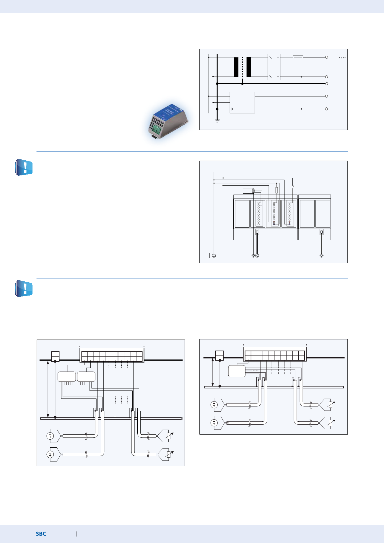
Saia PCD3 power supply and connection plan
External power supply
Grounding and connection plan for analog inputs that are not isolated electrically (PCD3.W2x0, PCD3.W3x0)
Connection concept for PCD3.W2x0
The reference potential of signal sources must be wired to a com-
mon GND distribution at the “-” terminal
Grounding and connection plan
Connection concept for PCD3.W3x0
The reference potential of voltage and current inputs must be
wired to a common GND distribution at the “-” terminal. Tem-
perature sensors must be wired to a common GND distribution
at the “COM” terminal.
Signal sources (such as temperature sensors) should be connected directly to the input module where possible.
The reference potentials of signal sources should be wired to a common GND connection (“–” and “COM” terminals). To obtain optimum
measurement results, any connection to a ground bar should be avoided. Additional external GND connections to the sensor signals may
result in equalizing currents which distort the measurement.
If shielded cables are used, the shield should be continued to a ground bar.
Using robust and interference-resistant SBC
power supply units with 24 VDC output is
generally recommended. For available types
see section 1.7 “accessories”.
For most modules, a full wave rectified power supply can be
used.
The following modules must be connected to
24 VDC smoothed:
PCD3. H1xx, H2xx, H3xx, PCD7.D2xx
The zero-potential (GND) of the 24 V supply is connected to the
GND and the controller’s grounding terminal. This should be con-
nected to the ground bar with the shortest possible wire (< 25 cm)
of 1.5 mm
2
. The same applies to the negative connection to the
PCD3.F1xx or the interrupt terminal.
Any shielding of analog signals or communication cables should
also be brought to the same grounding potential, either via a
negative terminal or via the ground bar.
All negative connections are linked internally. For problem-free
operation, these connections should be reinforced externally by
short wires with a cross-section of 1.5 mm
2
.
Transformer min. 50 VA
Voltage
regulator
2.5 mm
2
2.5 mm
2
W...
A...
E...
0 V +24 V
DC
Earthing bar
max. 25 cm
min. 2.5 mm
0...10 V
Pt/Ni 1000
Measuring
resistor
Measuring
resistor
Signal
source
Signal
source
Cable
with
Shield
Distributor
„V“ and„C“
Distributor
„Temp.“
Power PCD
Earthingbar
9 8 7 6 5 4 3 2 1 0
-
E7 E6 E5 E4 E3 E2 E1 E0
-
PGND
COM
0...10 V
Pt/Ni 1000
max. 25 cm
min. 2.5 mm
Measuring
resistor
Measuring
resistor
Signal
source
Signal
source
Cable
with
Shield
Distributor
Power PCD
Earthing bar
-
PGND
9 8 7 6 5 4 3 2 1 0
-
E7 E6 E5 E4 E3 E2 E1 E0


