134
saia-pcd.com
SBC
ref. Channel
ALE
―En
T1tot―
―Res 1
T1part―
―Res 2
T2tot―
T2part―
Tariff―
ComErr―
ref. Channel
AWD
―En
T1tot―
―
ResT1part―
ComErr―
ref. Channel
ALD
―En
Ttot―
―Res
Tpart―
Pa―
Pr―
U―
I―
ComErr―
ref. Channel
AWD/ALE
―En
U_L1―
U_L2―
U_L3―
I_L1―
I_L2―
I_L3―
Pa_L1―
Pa_L2―
Pa_L3―
Pr_L1―
Pr_L2―
Pr_L3―
CTratio―
ComErr―
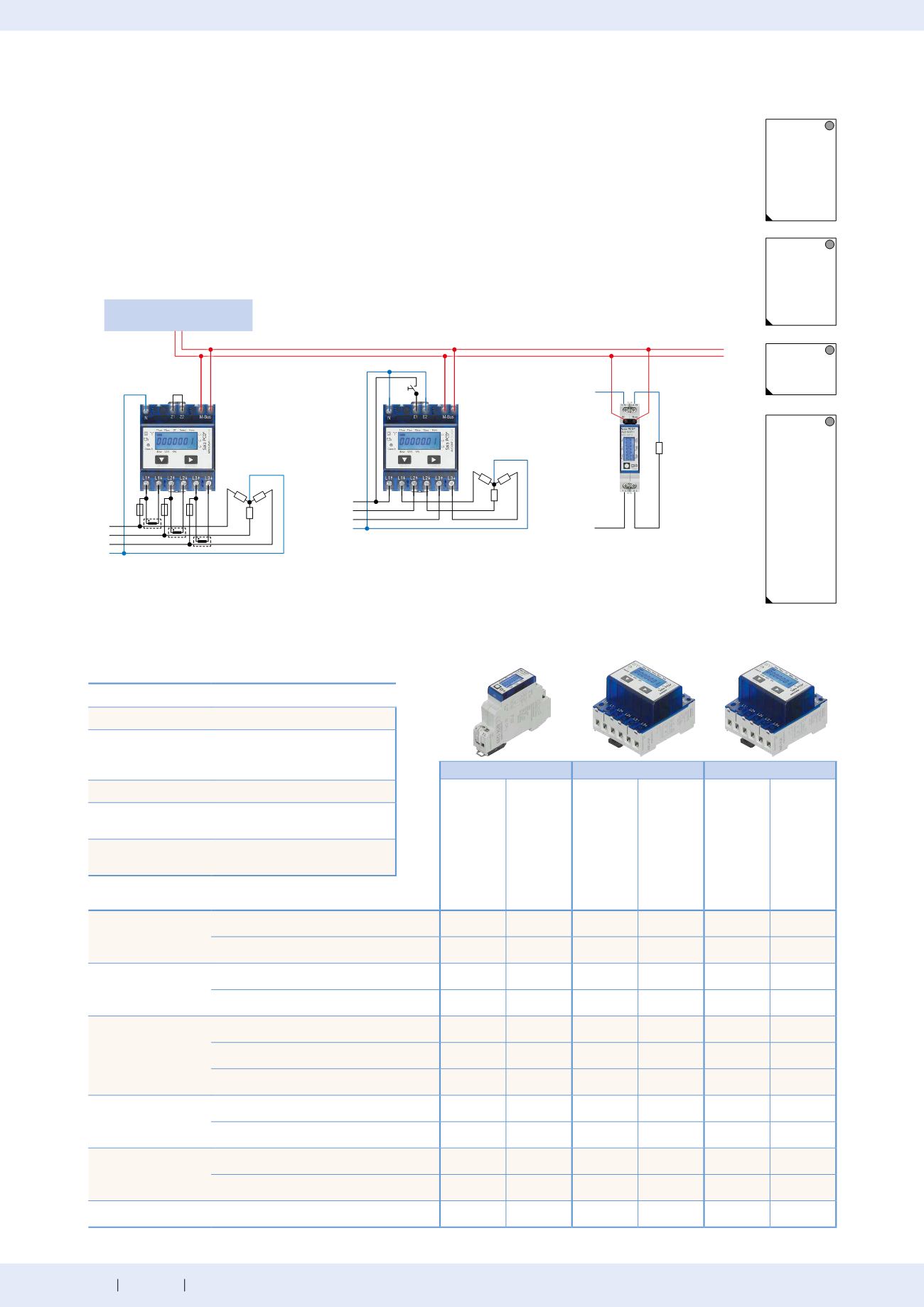
Saia PCD®
L1
L2
L3
N
(PEN)
L1
L2
L3
N
(PEN)
N
L
Consumption data collection
4.4.3
Saia PCD® energy meter with M-Bus interface
The M-Bus interface enables the connection and reading of measured data through any Saia PCD® or any M-Bus
Master. The meters correspond to M-Bus standard EN 13757. For connection to Saia PCD® systems, prefabricated
FBoxes are available free of charge for Saia PCD® energy meters. The relevant measurement data, such as energy,
current, voltage and output (active and reactive) can be read out via the M-Bus interface. On the display, the bus
primary address can be set and the energy, current, voltage and active output can be read directly.
ALD1
ALE3
AWD3
ALD1
D5FM00A2A00
ALD1
D5FM00A3A00
ALE3
D5FM10C2A00
ALE3
D5FM10C3A00
AWD3
D5WM00C2A00
AWD3
D5WM00C3A00
Tariff
1 tariff
–
–
2 tariffs
–
–
–
–
Approvals
With MID
–
–
–
Without MID
–
–
–
Rated/max. current
Current
I
min
= 0.05 A, I
N
= 5 A, I
max
= 6 A
–
–
–
–
I
min
= 0.25 A, I
N
= 5 A, I
max
= 32 A
–
–
–
–
I
min
= 0.5 A, I
N
= 10 A, I
max
= 65 A
–
–
–
–
Measurement type
Direct measurement
–
–
Conversion up to 1500 A
–
–
–
–
Operating voltage
230 VAC, 50 Hz
–
–
–
–
3 × 230/400 VAC, 50 Hz
–
–
Partial meter
Resettable
FBoxes available for
every M-Bus meter type
Technical Data
Connection diagram for M-Bus energy meters
Converter meter 3-phase
AWD3
Direct measurement 3-phase
ALE3
Direct measurement single-
phase ALD1
M-Bus
Bus system
M-Bus
Transmission rates
300, 2,400, 9,600 Baud.
The transmission rate is detected
automatically
Addressing
Primary and secondary
Bus length (max.)
In accordance with M-Bus
specifications
Response time
Write: up to 60 ms
Read: up to 60 ms


