161
saia-pcd.com
No123
No123
No123
3
SBC S-Web technology
SBC Software
2
Communication &
Interaction
1
SBC Software
Intuitive display as a function block diagram
User programs can be created from various FBoxes without any extensive knowledge of
programming. They can be displayed as desired in the function block diagram editor
(Fupla).
In this example, the performance values of individual energy meters are continually
monitored and the maximum and minimum values captured over days, weeks or even
years. The voltage and power is compared with variable limit values. If exceeded, a relay
output is activated which can be used, e.g., to control a signal lamp or to introduce a peak
load cut-out. In addition, an e-mail can be sent to notify a specialist.
Load cut-out
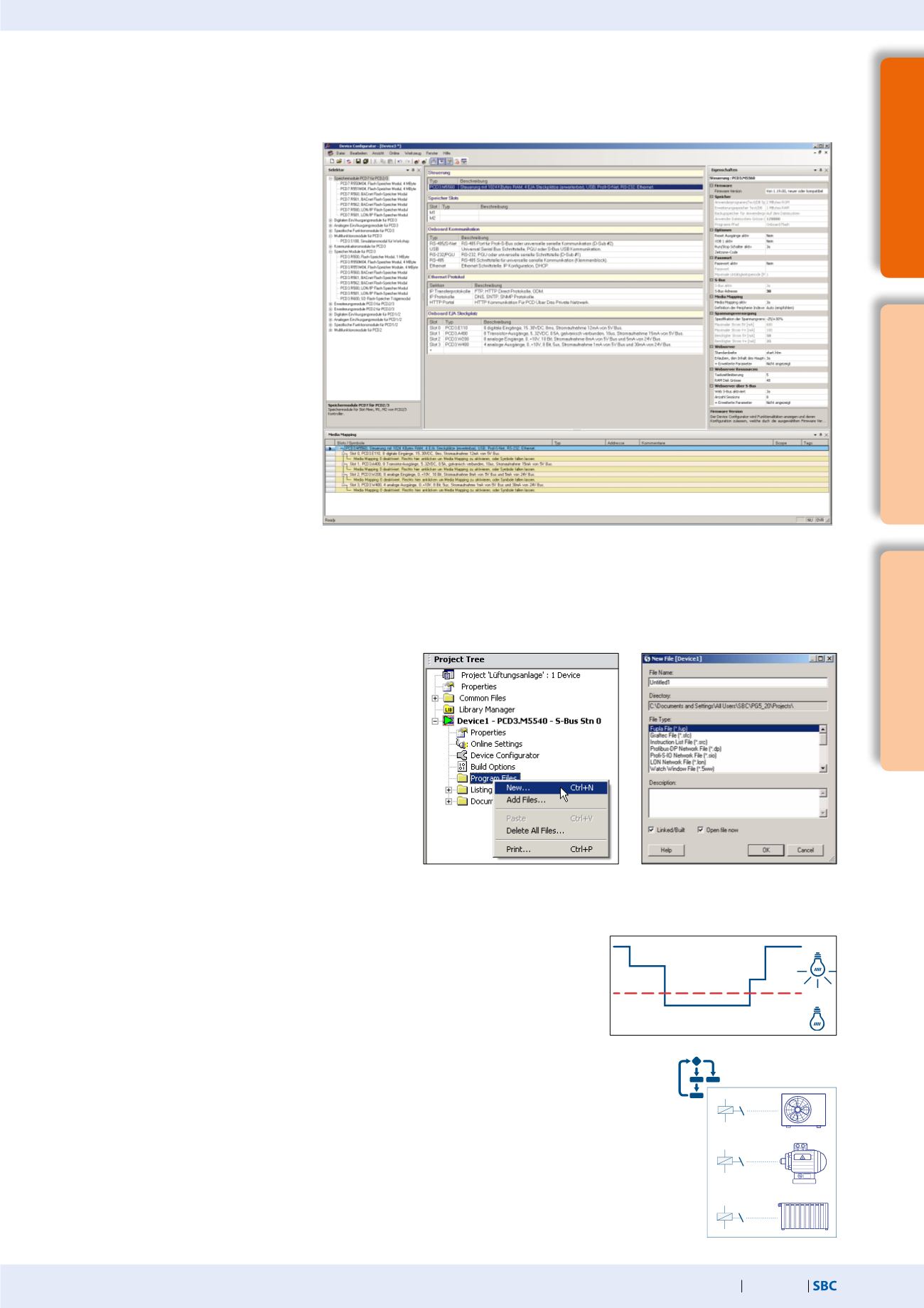
After the hardware settings, a new program file can be
created. Right-click on Program Files and then New in the
following selection menu.
The New File dialog opens. Enter
a file name. Make sure that Fupla Files (*.fup) is selected
as the File Type and close the dialog with OK.
Fupla file was created, now the user program can be
created with FBoxes.
Creating a Fupla file
The controller selection and the associated configuration are performed in the Device Configurator. The Device Configurator has
multiple windows: “Device View”, “Selector”, “Properties” and “Media Mapping”. The “Device View”window has a context menu. The menu
features various options, such as Device, memory slots, Monitoring, Onboard communication, Ethernet protocols and Onboard I/O slots.
The relevant components are selected in
the “Device View”window and all the
associated parameters displayed on the
right in the “Properties”window.
Parameters which can be edited can be
modified from here. If, for example, the
PCD3.M5540 device was selected in the
“Device View”window, the hardware
settings are displayed in the “Properties”
window. All modules which can be
inserted into one of the slots are listed in
the “Selector”window. This includes
digital and analogue I/O modules,
communications modules, expansion
modules, etc. Modules can be taken
from the “Selector”window and placed
in the device slots, whereby the relevant
slot is selected and then the module
double-clicked in the “Selector”window.
The module properties are configured
via the “Properties”window.
The “Media Mapping”window shows the symbol names for all inputs and outputs. The configuration of analog signals takes place here.
This window can be shown and/or hidden via the menu view
Media Mapping. After the settings have been performed, the configura-
tion must be loaded into the controller.
Device Configurator with the most important windows
An extract from the load cut-out is explained and presented below. Only the most important
FBoxes are dealt with here.
It should be made clear that a simple logic can be implemented with the FBoxes already in
the Saia PG5® Core.
Monitoring performance values


