86
saia-pcd.com
Standby Controller
Standby Controller
Standby System Overview
Introduction
The PCD3.M6880 Standby Controllers are for creating redundant automation solutions, to ensure the uninterrupted operation of sys-
tems and processes.
Standby (redundant automation) systems from SBC have the
following characteristics:
Based on the modular and robust PCD3 family, using standard
modules.
Simple system architecture to reduce costs.
Standby processors with shared Ethernet Remote I/Os
avoids the duplication of the inputs/outputs and the sensors/
actuators.
Programmable remote I/Os create intelligent decentralized
nodes to provide additional reliability.
The network uses standard Ethernet components, and can
run over a standard Ethernet TCP/IP network along with other
services.
Easy engineering and commissioning, using the PG5 Project
Manager to automatically generate the project.
Uninterrupted switching from Standby to Active device.
Standby controllers contain two processors. One processor
runs the redundant program and monitors the active PCD.
The second independent processor runs other non-redundant
processes. This significantly increases the performance and
flexibility of the system.
Comprehensive diagnostic features to aid commissioning and
fault finding.
Terminology
The following definitions will provide a better understanding of the properties and operating principles:
Standby Controller
The PCD3.M6880 controller which supports the standby feature.
Primary PCD
The PCD which becomes the active device by default when the system is powered up, depending on the
configuration.
Secondary PCD
The PCD which becomes the standby device on power up, and only takes over active control in the event of
a fault on the active device.
Active PCD
The PCD whose CPU1 is in Active Mode, running the redundant program and controlling the inputs/outputs
(PCD3.T668 RIOs).
Standby PCD
The PCD whose CPU1 is in Standby mode. It does not run the redundant program and the outputs
(PCD3.T668 RIOs) are not controlled by this device.
Main CPU
CPU0 of the Primary or the Secondary PCD, which runs the non-redundant program. This program may be
different on the Primary and Secondary devices.
Redundant CPU
CPU1 of the Primary or Secondary PCD, which contains the Redundant program. This program must be the
same on the primary and Secondary devices. This CPU is either in Active mode and running the Redundant
program, or in Standby mode and monitoring the Active PCD.
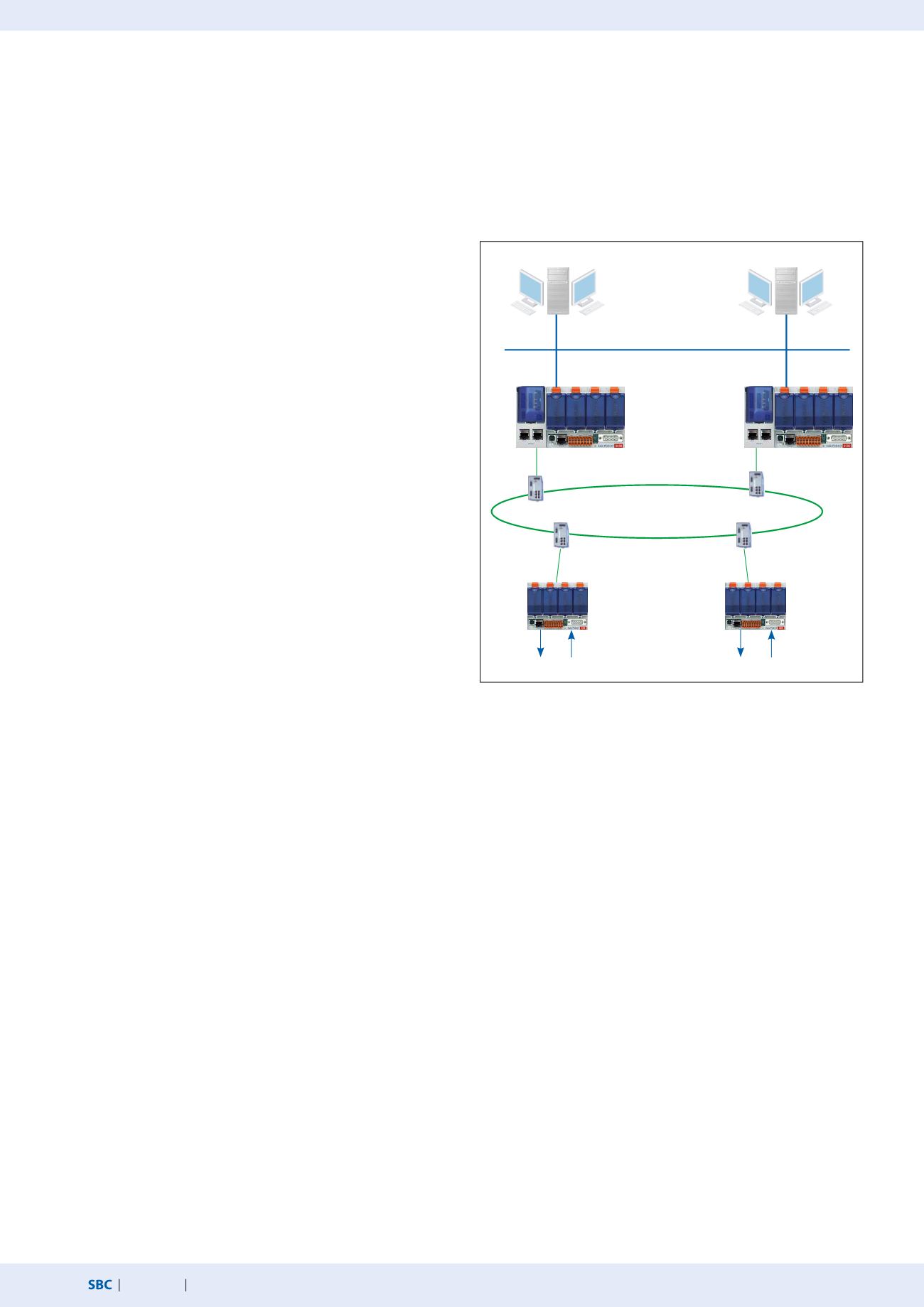
Network redundancy
with fiber optical ring
Typical layout of a redundancy system with two PCD3.M6880 Standby devices and
PCD3.T668 Ethernet Smart RIOs.
Secondary
Primary
SCADA system
Ethernet
Standby Controllers
PCD3.M6880
Smart RIOs
PCD3.T668
Process I/O
Process I/O
SCADA 1
SCADA 2


