91
saia-pcd.com
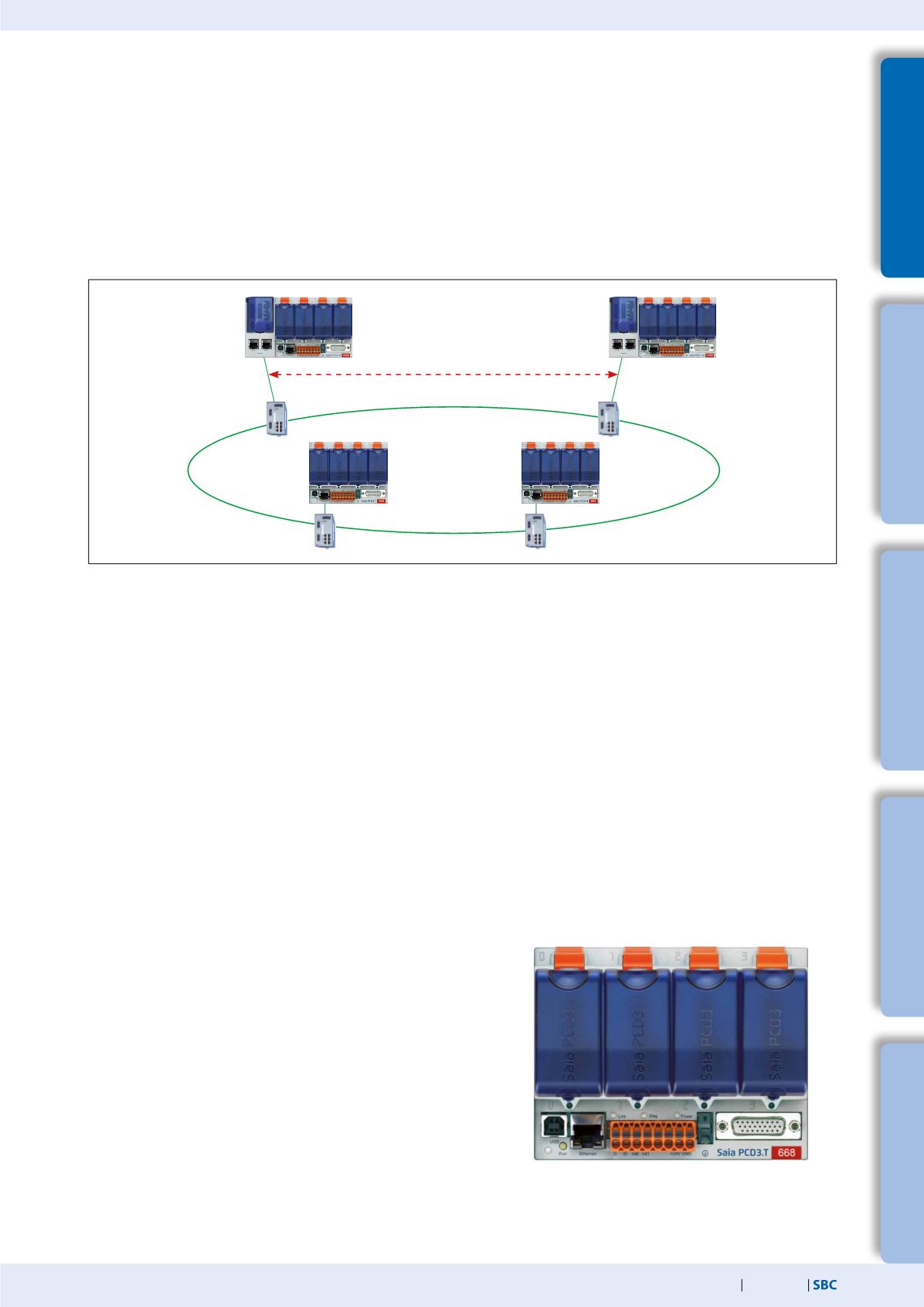
Standby Controller
Standby Controller
5
Switch cabinet
components
4
Consumer
data acquisition
3
Dedicated
room controllers
2
Operation
and monitoring
1
Automation
stations
Switchover Criteria
Each of the Standby PCDs (CPU1) sends a„Keep Alive“ telegram to its partner for supervision.
The STANDBY PCD switches to ACTIVE when:
No Keep Alive telegram has been received within the„Keep alive timeout“ period defined with the Redundant CPU‘s Device Configu-
rator. The “Keep Alive Timeout” can be adjusted between 100…500 ms. By this the max. switchover latency is <100…500 ms.
The ACTIVE PCD‘s state is not RUN or STOP (stops sending Keep Alive).
A manual Switchover command is executed. This is only possible if the Primary device does not have priority, the„Primary device has
priority“ option must be„No“.
1.6.2
PCD3.T668 Standby RIO
Architecture of the PCD3.T668
The PCD3.T668 remote I/Os are exclusively for use with the PCD3.M6880 Standby Controllers. With the exception of the redundancy
function, they support the same properties/functions as the PCD3.T666 remote I/O station. The PCD.T665 and PCD3.T666 standard
remote I/Os cannot be used with Standby Controllers.
Can be used as a simple local I/O station or an intelligent programmable
I/O station
Can be programmed with the PG5. Important or timecritical tasks can be
processed directly in the RIO
The RIO‘s user programs are managed centrally by the Smart RIO Manager
(PCD) and downloaded to the RIOs automatically
Data exchange uses the efficient Ether-S-IO protocol. Simple configuration
with the RIO Network Configurator
Cross-communication with other PCD systems using Ether-S-Bus (FBoxes)
Intelligent communication modules (e.g. M-Bus, DALI) are supported
Other communication protocols (e.g. Modbus) via Ethernet TCP/IP and
also by the onboard RS-485 interface
IntegratedWeb Server
Data Synchronization and Supervision (Keep Alive)
Data Synchronisation and Program Cycle:
The used PCD medias (R, F, T/C, DB/TX) in the redundant CPU1 are cyclically synchronized between the active and the standby PCD. The
synchronization time for all PCD media is normally less than 200 ms. This time is reduced accordingly if only a part of the PCD media is
used. The total program cycle time is calculated as follows:
Total cycle time = program execution time + data synchronization time
The max. value for a large application can be calculated as follows: 100 ms + 200 ms = 300 ms max.
For smaller applications where less PCD media are used the cycle time is reduced correspondingly.


