188
saia-pcd.com
SBC Software
Control
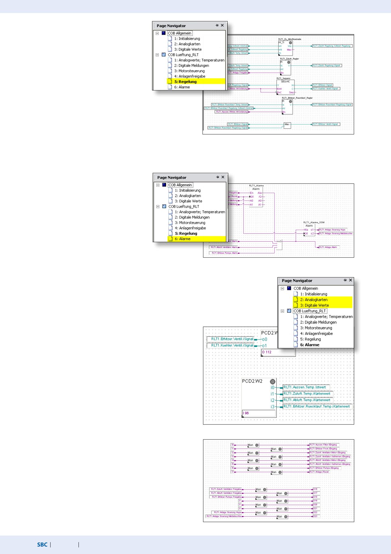
Alarms
Analog card
Digital values
Physical inputs and outputs for the test
Select the HVAC Analog family in the All or Application in the FBox
Selector tab. Place the FBox PCD2.W4 FBox and drag it to two
inputs. Place the FBox PCD2.W2 FBox and drag it to four inputs.
Connect all FBox inputs or outputs. Enter O 112 in the PCD2.W4
FBox. There must be a space behind O so that the exact output can
be identified. The same applies to I, F, R, etc. Enter I 96 in the FBox
PCD2.W2. Use drag & drop to drag the relevant icons from the
Symbol Editor into the connectors on the FBoxes.
Place the FBox Override binary from the FBox family HVAC General
on the page as shown. Set the connectors and connect all
elements as shown. In the Symbol Editor, add the symbol name I0
and 0 as the address.
Return to the symbol name and enter ..7 after the address I0 and
press Enter. The Symbol Editor will automatically create the
symbols I1 to I7 with the relevant address. Repeat this for the
digital outputs O16…23 with address 112 to 119. Now use drag
& drop to drag the available symbols into the connectors on the
Fupla page.
The symbols are now linked to inputs and outputs and can be
tested.
The Fupla program shown is a summary of a sample exercise
from the basic course from the building automation workshop.
Alarm processing
We still need to process messages as alarms.
Place the FBox Alarm inhibit 1–10 with two
inputs from the FBox family HVAC General FBox
Alarm on the page as shown. Then place the
FBox OR 2-10 inputs with 4 inputs in the FBox
family Binary Arithmetic, attach connectors and
connect all the elements as shown. The FBox
RLT1_Alarm saves the alarm until it is acknowl-
edged. As the motor alarms are already saved in
the FBox Motor, these can be connected via FBox OR to FBox
RLT_Alarm_SSM. The FBox RLT_Alarm_SSM is designed to provide
a visual and audible alarm notification. The S1 output is reset once
acknowledged and the S2 output switches from flashing to being
permanently on. Only once the alarm is deactivated will S2 also go
out.
Control
The system should receive a supply/exhaust air
temperature cascade as a control.
Place the FBox W/Room temperature from the
FBox family HVAC Setpoint, and the FBox
Controller PI and the FBox Sequence Master HC
in the FBox family HVAC Controllers on the page
as shown. Place the FBox Maximum and
connectors in the FBox family Integer Arithmet-
ics on the page as shown. Connect the elements. Now a few basic
settings still need to be made in the FBoxes. Click the FBox to open
the Properties window. All values are experience values which can
be used to control temperature as a basis for adjustment. These
values must be adjusted in accordance with the control behaviour
during operation.


