saia-pcd.com
118
PCD
7L
1 2 3 4 5
7 6
Y1 N Y2
1 2 3
Y3
0-10 V 2 mA
Y4
K1 K2
N V1
V3
V2
N L
N L
Valve
Option
A B 10 9 8 7 6 5 4 3
1 2
/D D
E2
E1 S
P1 E3
R 5V
Serial
Bus
Network
Aux.
Input
Window
Contact
Temp.
Sensor
Pot. Aux.
0-10 V
LED
RC
Service
Pin
230 V 800 mA
Made in EU
Power Supply
230 V
230 V
3 A
Valve
1/2
Fanspeed
3 steps
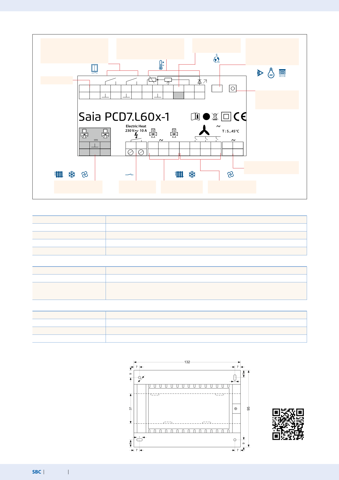
Dedicated room controllers
Terminal assignment (example PCD7.L601-1)
Technical Data
TRIAC output specification
10 mA…800 mA, maximum total current of both TRIACs
Current draw
Without actuator approx. 10 mA to 100 mA requires an external electrical back-up fuse
Protection
The module has to be installed in a locked box with aerations – minimum size: 240 × 145 × 100 mm
Dimensions W x H x D
132 × 95 × 45 mm
Temperature range
5…45 °C, 80% RH
Communication with S-Bus
Interface
RS-485, max. cable length of bus cable depends on baud rate, under ideal conditions up to max. 1200 m
Transmission rate
4,800, 9,600, 19,200, 38,400, 115,200 bit/s with automatic detection on restart
Log
SBC S-Bus data mode (slave)
Bus terminating resistors must be installed by the customer –
with integrated L60x these can be activated by software.
Communication with L
on
W
orks
®
Interface
FTT 10a
Transmission rate
78 kBit/s
Topology
Free topology max. 500 m, bus topology max. 2700 m
Number of L
on
nodes
Max. 64 per segment, over 32,000 in one domain / in accordance with L
on
M
ark
® 8020 profile
Dimensions for
PCD7.L60x-1
PCD7.L61x
PCD7.L62x
Mounting
On 35 mm DIN rail
Or with min. 2 × Ø 3 mm screws
on an even surface
Manuals and FBox library
Supply voltage
230 VAC
2× TRIAC outputs
230 VAC
Serial S-Net
2× analogue outputs
0…10 VDC
1× relay
output
2× digital inputs for isolated
contacts
– E1 window contact
– E2 parameterisable function
Analogue room control unit or
additional temperature sensor
NTC 10 kOhm
Internal data bus to con-
nect digital room control
devices or extension
modules
Button for
configuring the
S-Bus addresses
Outputs for 3-stage fan
230 VAC
1 × analogue input
0…10 VDC


