saia-pcd.com
112
PCD
7L
Dedicated room controllers
Project planning information
Maximum number of room controllers
The maximum number of room controllers that can be managed by a PCD system depends on the maximum electrical load of the serial
S-Net, the bus system cycle time and the resources used by the functional objects.
Types of use and modes of operation
The function of the room controller is based on various types of use or modes of operation.
Each of the selectable modes of operation can be assigned different control parameters.
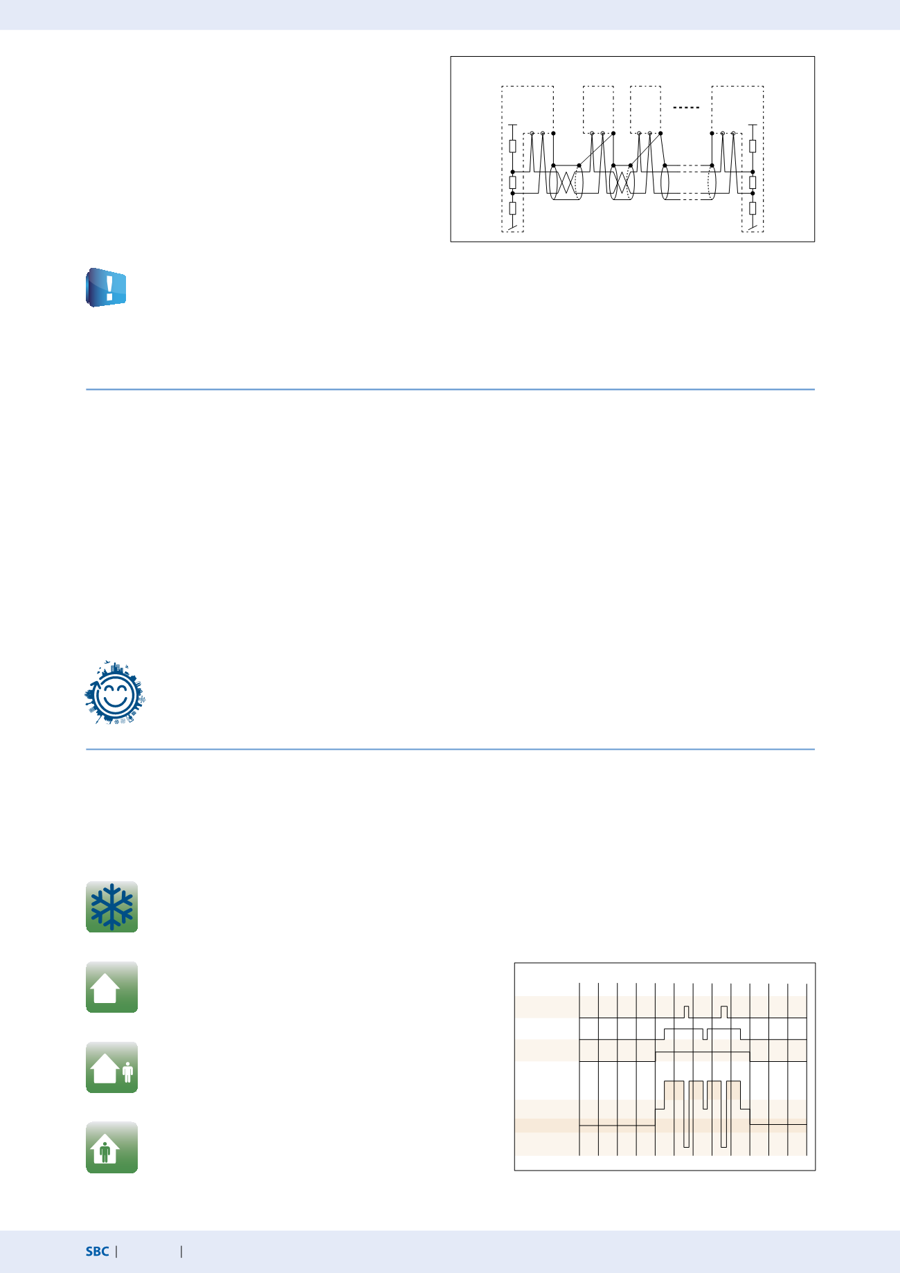
Bus terminating resistor and bus cable for serial S-Net
(S-Bus/RS-485)
S-Bus cables must be installed as a line. Stub lines are not per-
mitted and both ends of the cable must be terminated with
a resistor (approx. 120 Ω) between the D and /D cables. The
best signal quality is achieved using an active bus connection
with a resistor to +5V and GND.
Use/comfort
The room is used and should be brought to the comfort temperature.
This state can be reached by pressing the presence button, reacting
to an external presence detector or a parameter on the network side.
Window contact
open
Presence
detection
Room use time
program
Comfort
Standby
Reduced
Frost protection
0 h
2 h
4 h
6 h
8 h
10 h
12 h
14 h
16 h
18 h
20 h
22 h
24 h
Example: Operating mode switchover
Schematic illustration of an S-Bus/RS-485 bus
Safety mode/Frost protection
No heating or cooling energy is fed into the room. This state is desirable
if a window is open. The room controller keeps the room temperature
above the preset frost line of 8° C.
Non-use/reduced
Reduced operation mode which is used when the room is unoccupied
for long periods. The specified setpoint value offset is not active in this
operation mode.
Standby
The room is prepared for use but no presence has yet been registered
in the room. As long as the room is not classified as occupied by the
presence function, the room controller maintains the room temperature
within the specified limits at the standby temperature.
With S-Bus controllers, the 111 configuration register can be used to activate the integrated active bus terminating resistor or an
external PCD7.T161/2 termination box can be used.
Bus cable: A 2-strand twisted and shielded bus cable with cable strands of at least 0.5 mm2 must be used.
Bus shielding: The shielding of each S-Bus segment may only be connected with the electrical system ground at one point.
To avoid problems with large potential differences between the room controllers, the shielding of the S-Bus cable should be
connected with the GND of the room controller.
For more information, see S-Bus manual 26-739 (at
).
Recommendation: max. 4 S-Bus interfaces with up to 25 room controllers per interface so that resources are sufficient in most
cases and the communication cycle time remains <2 seconds
At a communication speed of 38,400 baud, the communication time for a controller is approx. 15 ms or 80 ms. If the PCD program
requires longer than 15 ms or 80 ms per PCD cycle, this value must be used as the basis of the calculation used to estimate the commu-
nication cycle. For additional information please refer to chapter 1.1.
Communication cycle = “15 ms or 80 ms per controller” × “Number of controllers”.
PCD7.L79xN
Resources
: approx. 2 kB (RAM) per controller, max. 40 registers per controller, max. 16 flags per controller
Bus cycle time per controller
: approx. 15 ms
PCD7.L60x-1 (when using all FBoxes)
Resources
: approx. 10 kB (RAM) per controller, max. 95 registers per controller, max. 36 flags per controller
Bus cycle time per controller
: approx. 80 ms
Start station
End station
Intermediate
stations
Pull down
Pull down
Terminating
resistor
Terminating
resistor
Pull up
Pull up
RS-485
S-Bus
+5V
+5V
/D D
/D D /D D
/D D


