29
saia-pcd.com
PCD
3
5540
F
2
6
1
1
0
F
2
6
1
8
W
3
4
0
100
W
3
4
0
W
3
4
0
W
6
1
0
E
1
6
0
100
W
3
4
0
W
3
4
0
W
6
1
0
E
1
6
0
E
1
6
E
1
6
E
1
6
SaiaPCD3.M
SaiaPCD3.C
SaiaPCD3.C
100
A
4
6
0
A
4
6
0
A
4
6
0
200
A
8
6
0
A
8
1
0
A
8
1
0
A
2
0
0
W
3
8
0
SaiaPCD3.C
SaiaPCD3.C
Automation stations – Saia PCD3
5
Switch cabinet
components
4
Consumer
data acquisition
3
Dedicated
room controllers
2
Operation
and monitoring
1
Automation
stations
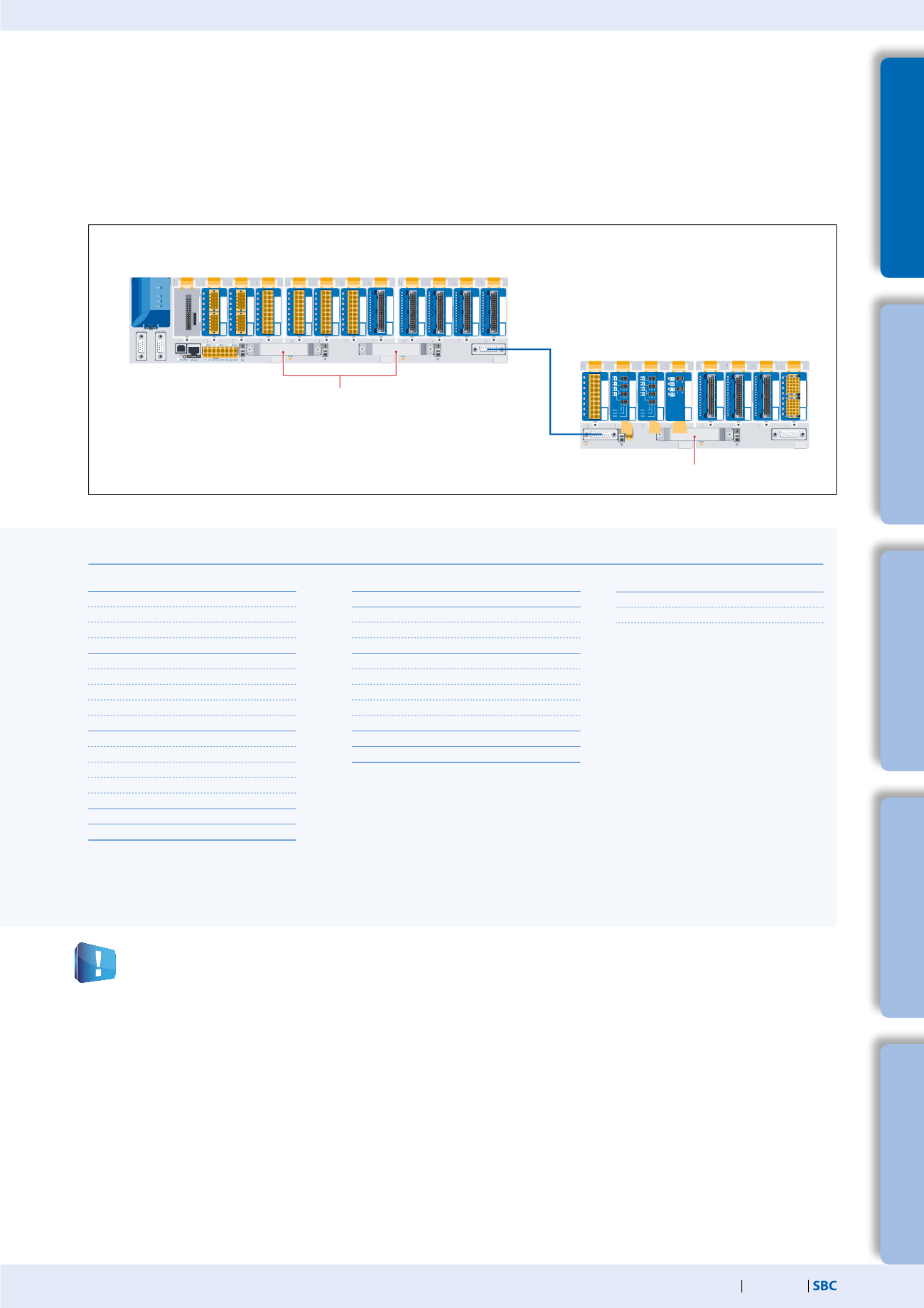
Information for project planning with PCD3 module holders
The internal load current taken by the I/O modules from the +5V and +V (24V) supply must not exceed the maximum supply current
specified for the CPUs, RIOs or PCD3.C200 module holders.
Example calculation for the current consumption of the internal +5V and +V (24V) bus of the I/O modules
The calculation example shows that internal capacity is maintained in the CPU basic mod-
ule PCD3.M5540 and the holder module PCD3.C200. The CPU basic module has a sufficient
reserve to receive an additional communication module in the empty slot 0. The holder
module PCD3.C200 also has sufficient reserves to connect an additional PCD3.C100 or
PCD3.C110 holder module. The power consumption of the internal +5V and +V (24 V) bus
for the I/O modules is automatically calculated in the PG5 2.0 Device Configurator.
The following aspects should be considered when planning PCD3 applications:
PCD3.M5540
CPU incl. 4 I/O slots
PCD3.C100
I/O module holder
4 slots
Extension plug
PCD3.K010
PCD3.C100
I/O module holder
4 slots
PCD3.C100
I/O module holder
4 slots
PCD3.C200
I/O module holder
4 slots
Extension cable
PCD3.K106
Extension plug PCD3.K010
Consumption C200 + C100
Module
Internal 5V
Internal +V (24V)
A200
15 mA
A810
40 mA
A810
40 mA
A860
18 mA
Total C200 113 mA
A460
10 mA
A460
10 mA
A460
10 mA
W380
25 mA 25 mA
Total C100 55 mA 25 mA
Total C200 168 mA 25 mA
Capacity
PCD3.M5540 PCD3.C200
Internal 5V
600 mA
1500 mA
Internal +V (24V) 100 mA
200 mA
Consumption M5540 + C100 + C100
Module
Internal 5V Internal +V (24V)
Not used
F210
110 mA
F281
90 mA 15 mA
W340
8 mA 20 mA
Total M5540
208 mA 35 mA
W340
8 mA 20 mA
W340
8 mA 20 mA
W610
110 mA
0 mA
E160
10 mA
Total C100
136 mA 40 mA
E160
10 mA
E160
10 mA
E160
10 mA
E160
10 mA
Total C100
40 mA
0
Total M5540 384 mA 75 mA
In keeping with lean automation, it is recommended to leave
the first slot in the CPU basic module free for any subsequent
expansions. Both single I/O modules and communication
modules can be used in this slot.
The total length of the I/O bus is limited by technical factors;
the shorter, the better.
The PCD3.C200 is used to extend the I/O bus or for the internal
power supply (+5V and +V (24V)) to a module segment.
Please note the following rules:
Do not use more than six PCD3.C200s in a single configuration,
or the time delay will exceed the I/O access time.
Use a maximum of five PCD3.K106/116 cables.
Insert a PCD3.C200 after each cable (at the start of a row).
Exception: In a small configuration with no more than
3 PCD3.C1xxs, these can be supplied from the PCD3.Mxxx.
A PCD3.C200 is not required.
If an application is mounted in a single row (max. 15 module
holders), then after five PCD3.C100 a PCD3.C200 must be used
to amplify the bus signal (unless the configuration ends with
the fifth PCD3.C100).
If the application is mounted in multiple rows, the restricted
length of cable means that only three module holders
(1× PCD3.C200 and 2× PCD3.C100) may be mounted in one
row.


