28
saia-pcd.com
PCD
3
Automation stations – Saia PCD3
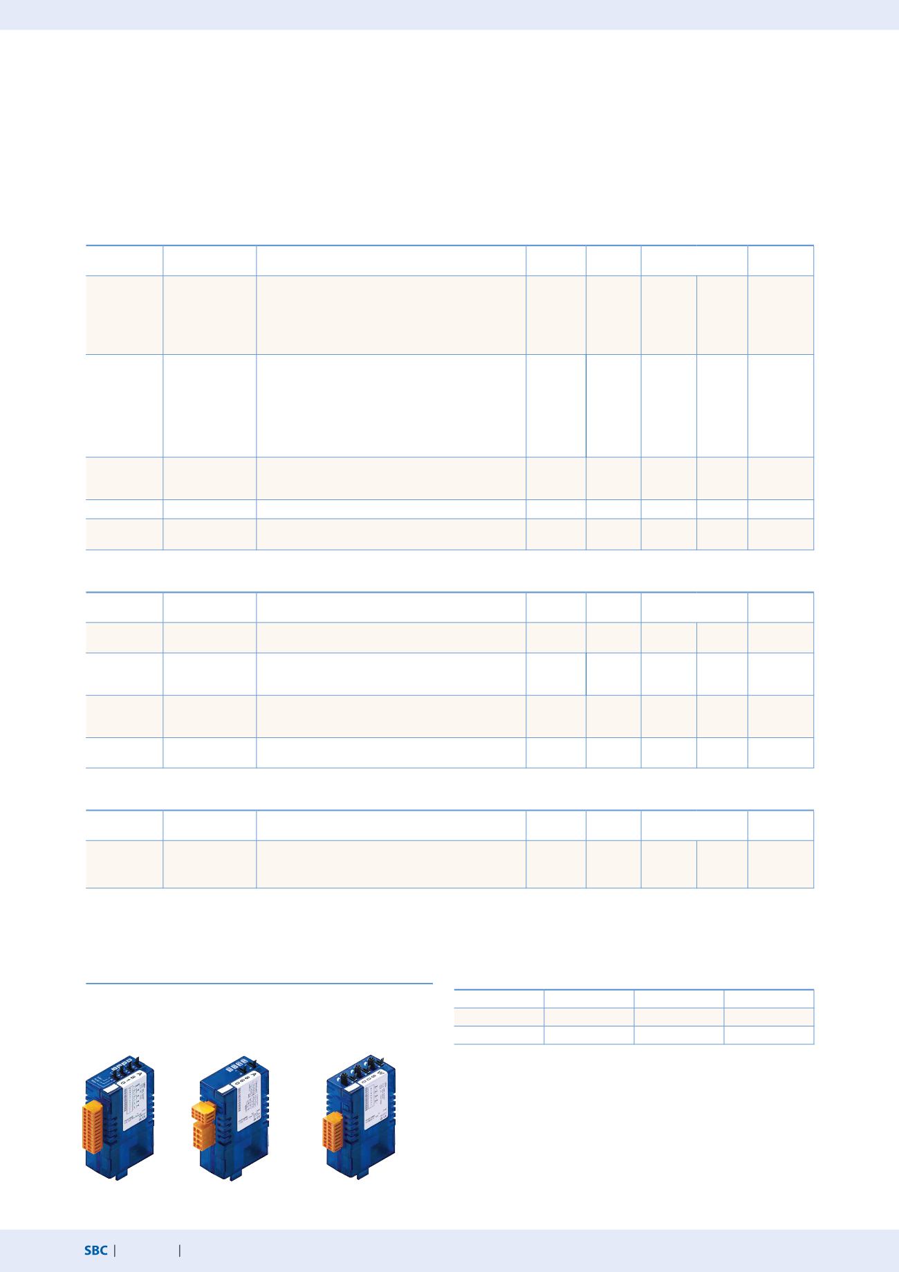
Saia PCD3 analogue input and output modules
The numerous analogue modules allow complex control tasks or measurements to be performed. The resolution is between 8 and
16 bits, depending on the speed of the AD converter. The digitised values can be further processed direct in the project in the
Saia PCD3. The large number of different modules means that suitable modules are available for almost any requirement.
Manual control modules
Analogue input modules
Type
Total
Channels
Signal ranges/description
Resolution Electrical
isolation
Internal current draw
5 V-Bus
1)
+ V-Bus
2)
I/O connec-
tor type
3)
PCD3.W200
PCD3.W210
PCD3.W220
PCD3.W220Z03
PCD3.W220Z12
8 I
8 I
8 I
8 I
4 I
4 I +
0…+10 V
0…20 mA
4)
Pt1000: –50°C…400°C/Ni1000: –50°C…+200°C
NTC 10 temperature sensor
4 I: 0…10 V
4 I: Pt1000: –50°C…400°C/Ni1000: –50°C…+200°C
10 Bit
10 Bit
10 Bit
10 Bit
10 Bit
---
8 mA
8 mA
8 mA
8 mA
8 mA
5 mA
5 mA
16 mA
16 mA
11 mA
A
A
A
A
A
PCD3.W300
PCD3.W310
PCD3.W340
PCD3.W350
PCD3.W360
PCD3.W380
8 I
8 I
8 I
8 I
8 I
8 I
0…+10 V
0…20 mA
4)
0…+10 V/0…20 mA 4)
Pt1000: –50°C…400°C/Ni1000: –50°C…+200°C
Pt100: –50°C…+600°C/Ni100: –50°C…+250°C
Pt1000: –50°C…+150°C
–10 V…+10 V, –20 mA…+20 mA, Pt/Ni1000, Ni1000 L&S,
NTC10k/NTC20k (configuration using software)
12 Bit
12 Bit
12 Bit
12 Bit
12 Bit
13 Bit
---
8 mA
8 mA
8 mA
8 mA
8 mA
25 mA
5 mA
5 mA
20 mA
30 mA
20 mA
25 mA
A
A
A
A
A
2× K
PCD3.W305
PCD3.W315
PCD3.W325
7 I
7 I
7 I
0…+10 V
0…20 mA
4)
–10 V…+10 V
12 Bit
12 Bit
12 Bit
●
●
●
60 mA
60 mA
60 mA
0 mA
0 mA
0 mA
I
I
I
PCD3.W720
2 I
Weighing module with 2 systems for up to 6 weighing cells
≤18 Bit
---
60 mA 100 mA
I
PCD3.W745
4 I
Temperature module for TC type J, K and 4-wire Pt/Ni
100/1000
16 Bit
●
200 mA 0 mA
6)
Analogue output modules
Type
Number of
channels
Signal ranges/description
Resolution Electrical
isolation
Internal current draw
5 V-Bus
1)
+ V-Bus
2)
I/O connec-
tor type
3)
PCD3.W400
PCD3.W410
4 O
4 O
0…+10 V
0…+10 V/0…20 mA/4…20 mA jumper-selectable
8 Bit
8 Bit
---
1 mA
1 mA
30 mA
30 mA
A
A
PCD3.W600
PCD3.W610
4 O
4 O
0…+10 V
0…+10 V/–10 V…+10 V/0…20 mA/4…20 mA jumper-
selectable
12 Bit
12 Bit
---
4 mA
110 mA
20 mA
0 mA
A
A
PCD3.W605
PCD3.W615
PCD3.W625
6 O
4 O
6 O
0…+10 V
0…20 mA/4…20 mA parameters can be set
–10 V…+10 V
10 Bit
10 Bit
10 Bit
●
●
●
110 mA
55 mA
110 mA
0 mA
0 mA
0 mA
I
I
I
PCD3.W800
4 O, 3 of which are
manually operated
0…+10 V, short circuit-proofed
10 Bit
---
45 mA 35 mA
5)
J
Analogue input/output modules
Type
Number of
channels
Signal ranges/description
Resolution Electrical
isolation
Internal current draw
5 V-Bus
1)
+ V-Bus
2)
I/O connec-
tor type
3)
PCD3.W525
4 I +
2 O
I:
0…10 V, 0(4)…20 mA, Pt1000, Pt500 or Ni1000
(selectable via DIP switch)
O:
0…10 V or 0(4)…20 mA (selectable via software)
I: 14 Bit
O: 12 Bit
●
40 mA 0 mA
I
PCD3.A810
Relay outputs, 2 change-
over and 2 make
PCD3.A860
Light and shade 2 relay
outputs and 2 inputs
PCD3.W800
4 analogue outputs
(3 of these operable)
3)
Plug-in I/O terminal blocks are included with I/O modules.
Spare terminals, ribbon connectors with system cables and separate terminals
are ordered as accessories (see pages 34 and 160).
4)
4…20 mA via user program
5)
At 100% output value and 3 kΩ load
6)
With soldered spring terminal block
Overview of the internal bus capacity of the module holders
Capacity
PCD3.Mxxx0
PCD3.Txxx
PCD3.C200
1)
Internal 5V
600 mA
600 mA
1500 mA
2)
Internal +V (24 V)
100 mA
100 mA
200 mA
The electrical requirement of the internal +5V and +V bus for the I/O modules is
calculated in the PG5 Device Configurator.


