20
saia-pcd.com
PCD
3
180
28.5
63.8
125.8
139
67.3
100.5
35
32.8
32.7
130
5540
Saia PCD3.M
Automation stations – Saia PCD3
With the left expansion, the Standard (PCD3.M5/M6xxx) and High Power (PCD3.Mxx60) CPU types have slots for a battery holder
module with LED indicators, a run/stop switch, two slots for flash memory modules and two additional communication interfaces.
The LED indicators on the battery module display the status of the CPU and battery and any errors in the application. The battery
also protects the data in the event of an interruption to the power supply. It can be replaced during operation while under power.
The configuration, programs and data can be transferred from one controller to another using the plug-in flash memory modules.
No programming tool is required for this.
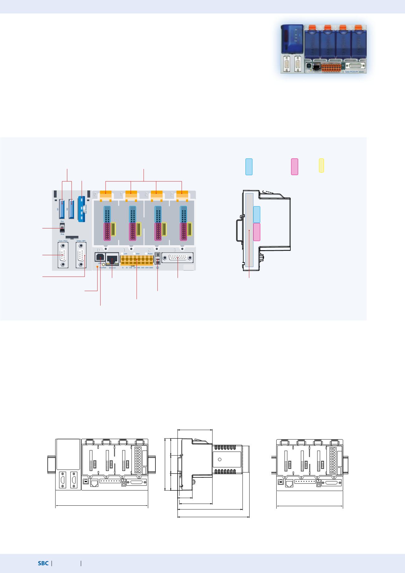
Design of Saia PCD3 controllers
PCD3.Mxxxxx base unit
Base unit with CPU and 4 slots for I/O modules, communication or other specific modules (e.g. PCD3.Hxxx counter modules)
Dimensions
Standard and High Power CPU with slots for battery
and memory modules, run/stop switch and additional
interfaces
PCD3.M5xx0/M6xx0
PCD3.M3xx0 without left expansion
Minimum Basic CPU without battery module.
PCD3.Rxxx memory modules are plugged into
an I/O slot.
Expansion connection
for I/O module holder
24 VDC power supply, RS-485
interface (Port 2),Watchdog
relay, interrupt inputs
Earth connection
USB connection
Ethernet
connection
RUN/STOP
switch
4 slots for I/O modules, communication modules or
other intelligent modules
Battery
module
Memory modules
RUN/STOP LED
indicator
RS-232 PGU
(Port 0)
RS-422/485 (Port
3 or 10)
The CPU has been incorporated into the back panel of the device, unlike comparable
systems. Its capacity can be increased individually with plug-in communication modules
and/or intelligent I/O modules. These have a direct, very fast bus connection to the CPU.
The CPU is incorporated into the back
panel. An additional 4 I/O modules can
therefore be inserted into the same area.
I/O bus for
standard
modules
Fast serial bus (SPI) for
running up to 4 intel-
ligent modules
Ground con-
nection for I/O
modules
180 × 100.5 × 139 mm (W × H × D)
130 × 100.5 × 139 mm (W × H × D)
Device design


