28
saia-pcd.com
PCD
3
Automationsstationen – Saia PCD3
Saia PCD3 analoge Ein- und Ausgangsmodule
Die zahlreichen Analogmodule lassen komplexe Regelungen oder Messungen zu. Die Auflösung beträgt dabei je nach Geschwindigkeit
des AD-Wandlers zwischen 8 und 16 Bit. Die digitalisierten Werte lassen sich in der Saia PCD3 direkt im Projekt weiterverarbeiten. Durch
die grosse Anzahl an unterschiedlichen Modulen lassen sich für nahezu jeden Anforderungsbereich passende Module finden.
Handbedienmodule
Analoge Eingangsmodule
Typ
Anzahl
Kanäle
Signalbereiche / Beschreibung
Auflösung
Galv.
Trennung
Interne
Stromaufnahme
5 V-Bus
1)
+ V-Bus
2)
E/A-
Stecker-
typ
3)
PCD3.W200
PCD3.W210
PCD3.W220
PCD3.W220Z03
PCD3.W220Z12
8 E
8 E
8 E
8 E
4 E
+ 4 E
0…+10 V
0…20 mA
4)
Pt1000: –50°C…400°C/Ni1000: –50°C…+200°C
NTC10–Temperaturfühler
4 E: 0…10 V
4 E: Pt1000: –50°C…400°C/Ni1000: –50°C…+200°C
10 Bit
10 Bit
10 Bit
10 Bit
10 Bit
---
8 mA
8 mA
8 mA
8 mA
8 mA
5 mA
5 mA
16 mA
16 mA
11 mA
A
A
A
A
A
PCD3.W300
PCD3.W310
PCD3.W340
PCD3.W350
PCD3.W360
PCD3.W380
8 E
8 E
8 E
8 E
8 E
8 E
0…+10 V
0…20 mA
4)
0…+10 V/0…20 mA
4)
Pt1000: –50°C…400°C/Ni1000: –50°C…+200°C
Pt100: –50°C…+600°C/Ni100: –50°C…+250°C
Pt1000: –50°C…+150°C
–10 V…+10 V, –20 mA…+20 mA, Pt/Ni1000, Ni1000 L&S,
NTC10k/NTC20k (Konfiguration über Software)
12 Bit
12 Bit
12 Bit
12 Bit
12 Bit
13 Bit
---
8 mA
8 mA
8 mA
8 mA
8 mA
25 mA
5 mA
5 mA
20 mA
30 mA
20 mA
25 mA
A
A
A
A
A
2× K
PCD3.W305
PCD3.W315
PCD3.W325
7 E
7 E
7 E
0…+10 V
0…20 mA
4)
–10 V…+10 V
12 Bit
12 Bit
12 Bit
●
●
●
60 mA
60 mA
60 mA
0 mA
0 mA
0 mA
E
E
E
PCD3.W720
2 E
Wiegemodule, 2 Systeme für bis zu 6 Wiegezellen
≤18 Bit
---
60 mA 100 mA
E
PCD3.W745
4 E
Temperaturmodul für TC Typ J, K und 4-Leiter Pt/Ni100/1000 16 Bit
●
200 mA 0 mA
6)
Analoge Ausgangsmodule
Typ
Anzahl
Kanäle
Signalbereiche/Beschreibung
Auflösung
Galv.
Trennung
Interne
Stromaufnahme
5 V-Bus
1)
+ V-Bus
2)
E/A-
Stecker-
typ
3)
PCD3.W400
PCD3.W410
4 A
4 A
0…+10 V
0…+10 V/0…20 mA/4…20 mA wählbar mit Jumper
8 Bit
8 Bit
---
1 mA
1 mA
30 mA
30 mA
A
A
PCD3.W600
PCD3.W610
4 A
4 A
0…+10 V
0…+10 V/–10 V…+10 V/0…20 mA/4…20 mA
wählbar mit Jumper
12 Bit
12 Bit
---
4 mA
110 mA
20 mA
0 mA
A
A
PCD3.W605
PCD3.W615
PCD3.W625
6 A
4 A
6 A
0…+10 V
0…20 mA/4…20 mA parametrierbar
–10 V…+10 V
10 Bit
10 Bit
10 Bit
●
●
●
110 mA
55 mA
110 mA
0 mA
0 mA
0 mA
E
E
E
PCD3.W800
4 A, davon 3 mit
Handbedienung
0…+10 V, kurzschlussfest
10 Bit
---
45 mA 35 mA
5)
J
Analoge Ein-/Ausgangsmodule
Typ
Anzahl
Kanäle
Signalbereiche/ Beschreibung
Auflösung
Galv.
Trennung
Interne
Stromaufnahme
5 V-Bus
1)
+ V-Bus
2)
E/A-
Stecker-
typ
3)
PCD3.W525
4 E
+
2 A
E:
0…10 V, 0(4)…20 mA, Pt1000, Pt500 oder Ni1000
(auswählbar über DIP-Schalter)
A:
0…10 V oder 0(4)…20 mA (auswählbar über Software)
E: 14 Bit
A: 12 Bit
●
40 mA 0 mA
E
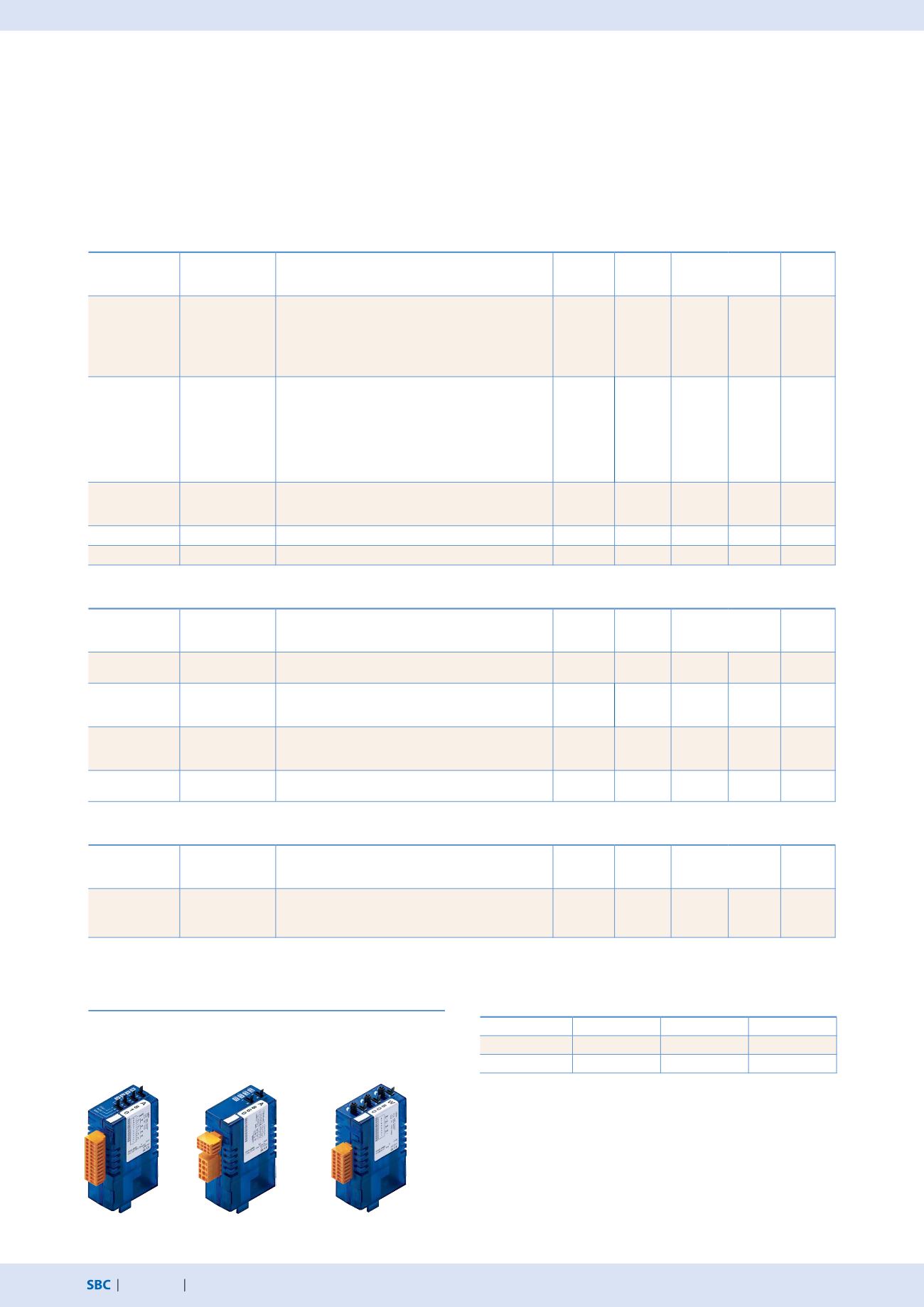
PCD3.A810
Relaisausgänge,
2 Umschalter und
2 Schliesser
PCD3.A860
Licht und Beschattung
2 Relaisausgänge und
2 Eingänge
PCD3.W800
4 analoge Ausgänge
(3 davon bedienbar)
3)
Die steckbaren E/A-Klemmenblöcke sind im Lieferumfang der E/A-Module
enthalten. Ersatzklemmen, Flachbandstecker mit Systemkabel und separate
Klemmenadapter werden als Zubehör bestellt (siehe Seiten 34 und 172).
4)
4…20 mA über Anwenderprogramm
5)
Bei 100% Ausgabewert und 3 kΩ Last
6)
Nicht steckbarer Federkraftklemmenblock
Übersicht interne Busbelastbarkeit der Modulträger
Belastbarkeit
PCD3.Mxxx0
PCD3.Txxx
PCD3.C200
1)
Intern 5 V
600 mA
600 mA
1500 mA
2)
Intern +V (24 V)
100 mA
100 mA
200 mA
Die Strombedarfsberechnung vom internen +5V und +V-Bus für die
E/A-Module erfolgt im Device-Konfigurator vom PG5.


