155
saia-pcd.com
PCD7.L291
PCD7.L490 / PCD7.L290
Switch cabinet components
5
Switch cabinet
components
4
Consumer
data acquisition
3
Dedicated
room controllers
2
Operation
and monitoring
1
Automation
stations
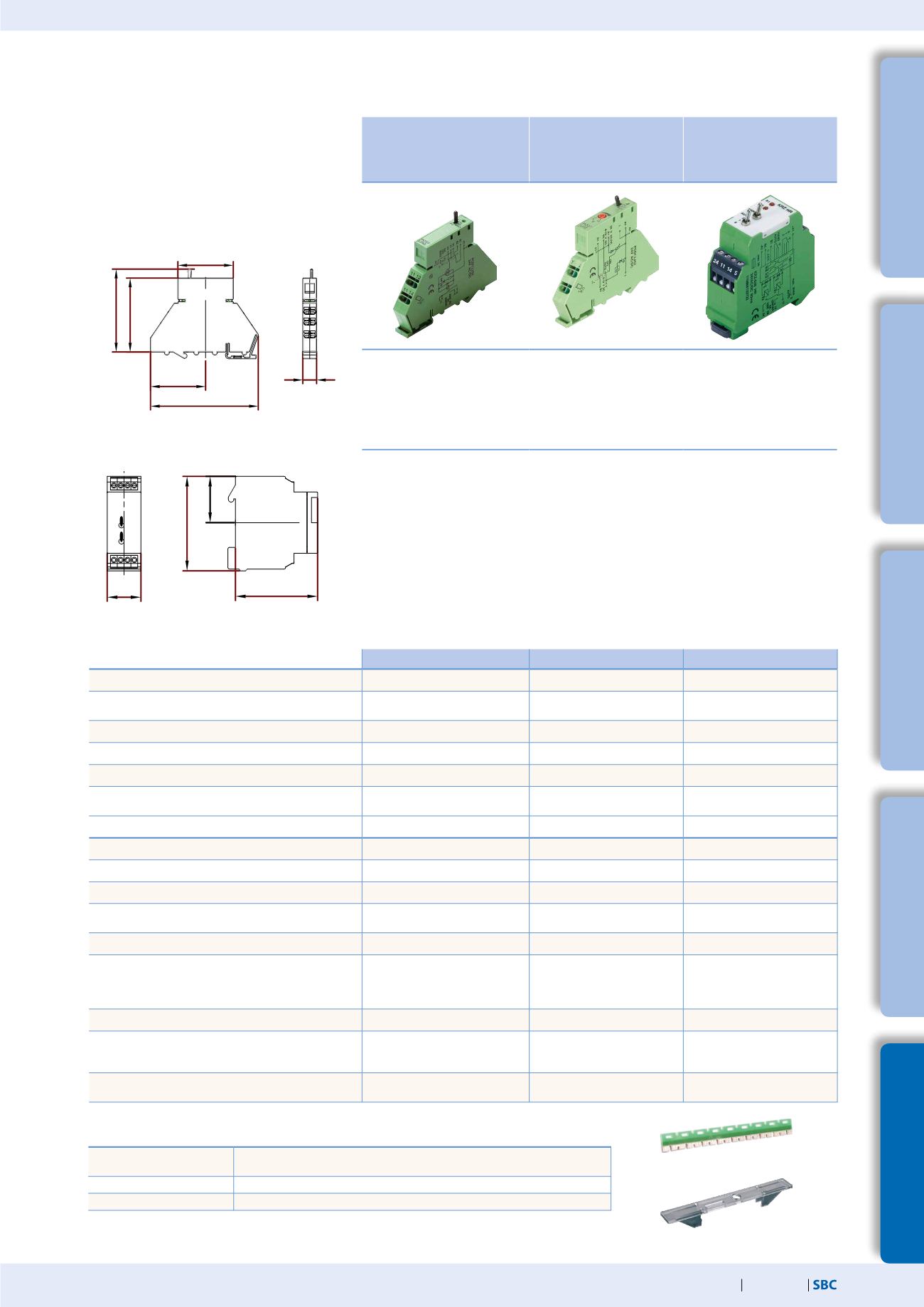
PCD7.L252:
Coupler modules with
manual operating level
Auto/OFF/ON
PCD7.L452:
Analogue value
transmitter for manual
correcting variables
PCD7.L260:
Coupler module for
two-stage motor
control
1 changeover contact
Local override operation
Auto acknowledge
LED display
Test contacts for each terminal
Spring terminals (push-in)
Potentiometer 0…10 V
Local override operation
Auto acknowledge
LED brightness in proportion to
control variable
Test contacts for each terminal
Spring terminals (push-in)
Interlocked relay
Local override operation
Auto acknowledge
LED display
Screw terminals
Single-stage coupler component
with local override operation, ack-
nowledgement of switch position
and an LED for status indication.
Coupler modules are used for safe
potential isolation between logic
and load.
Spring terminals allow for quick
and easy wire connection.
The supply voltage can be
connected across jumpers using
additional terminals with no wiring
or additional time required.
The analogue data encoder is
used as a variable encoder for
manual variable specification, e.
g. mixing valves, valve positions,
temperature values, etc. It has
three operating modes: ON, OFF
and AUTO. In switch position
AUTO, the control variable will be
looped unchanged via the YR ter-
minal to the control variable out-
put Y. In switch position ON, the
control variable can be set using
the potentiometer on the front of
the device. The output signal will
be available at terminal Y.
This coupler module is used for
switching units, pumps, fans,
etc. When switching back from
stage 2 to stage 1, stage 2 is
first switched off and stage 1
is switched on after a delay of
<60 ms. A manual control level
has been integrated for service
purposes. The time function is
operational here too.
Input side
PCD7.L252
PCD7.L452
PCD7.L260
Supply voltage
24 VDC/VAC, –15%/+10%
24 VDC/VAC, –15%/+20% 24 VDC/VAC, ±10%
Current draw
13 mA, protection wiring with
recovery diode
19 mA at 24 VDC
30 mA at 24 VAC
30 mA
Input current
---
2 mA at 10 VDC (input YR)
max. 4 mA, terminal B1/B2
Response / release time
10 ms/5ms
---/---
20 ms/20 ms
Input voltage
24 VDC/VAC
0…10 VDC
24 VDC/VAC
Operating indicator
Green LED to indicate relay state Red LED (brightness in
proportion to control variable)
Two red LEDs to indicate relay
state
Output side
Output contact
1 changeover
---
1 changeover with 0 position
Turn-on voltage
max. 250 VDC/VAC
---
Max. 250 VDC/VAC
On/off switching current
max. 8A
---/---
Max. 6A
Output voltage
---
0…10 VDC, 10 mA, output Y in
switch position Auto/ON
---
Continuous current
8 A
---
4A
Breaking capacity (ohmic load)
24 VDC/180 W
50 VDC/65 W
230 VDC/50 W
250 VAC/2000 VA
---
---
---
—
24 VDC/150W
50 VDC/25W
230 VDC/50W
230 VAC/1500 VA
Breaking capacity min.
24 VDC/20 mA
—
24 VDC/20 mA
Service life
mechanical
electrical (at maximum switching load)
2×10
7
switch cycles
1×10
5
hystereses
---
---
1×10
7
switch cycles
1×10
5
hystereses
Switching frequency
MAX: 300 hystereses / h at max.
current
---
MAX: 1,200 hystereses / h at
max. current
5.5
SBC interface modules with local override
to control drives, valves or flap systems
Accessories
PCD7.L291
Jumper for connection of the supply voltage of up to 10 PCD7.L252 and PCD7.
L452 modules
PCD7.L490
Labelling plate for PCD7.L452 (in packs of 10)
PCD7.L290
Labelling plate for PCD7.L252 (in packs of 10)
22.5
60
60
30
60
11.2
88
44
43
67.3
PCD7.L252/452
PCD7.L260
Dimensions


