164
saia-pcd.com
Switch cabinet components
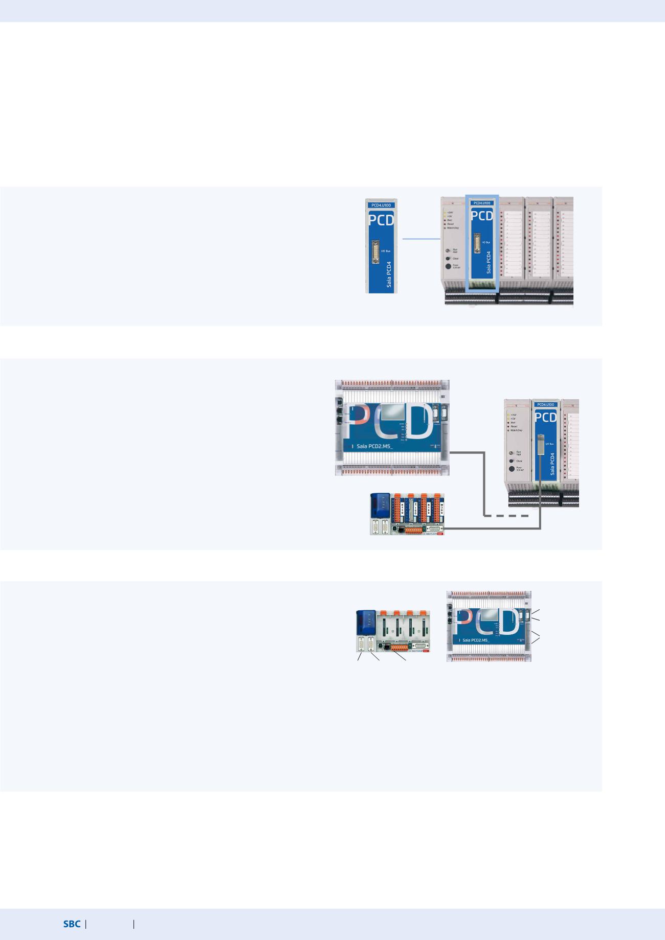
Saia PCD4.U100 upgrade kit
Once it has been clarified whether all I/O modules are suitable for upgrading, installation is really easy: Replace Saia PCD4 CPU with
PCD4.U100, install Saia PCD3 or PCD2 CPU, connect existing PCD4 I/Os.
1. Insert PCD4.U100 module
The existing PCD4 CPU is completely removed. To continue to
ensure I/O bus supply, the PCD4 supply module is still used.
The new PCD4.U100 module is used instead of the PCD4 CPU.
The existing power supply module PCD4.N2x0 must have at
least the hardware version “B”.
4. Programming with PG5
Transfer user program to PG5, adjust programs,
download and you’re done. Detailed descriptions of
the individual steps are listed in the PCD4.U100 manual.
3. Serial interfaces
None of the PCD4 serial interfaces are supported.
They must all be replaced with new PCD2/3 interfaces.
Maximum of 3 integrated serial interfaces on the PCD3.
Maximum of 4 integrated serial interfaces on the PCD2.
Additional expansion option with PCD3.F1xx or
PCD3.F2xx/PCD2.F2xxx*.
2. Connect PCD2.M5_ or PCD3.M_
The new PCD CPU is connected to the PCD4.U100 module
with the I/O bus cable. For PCD2.M5xxx: PCD2.K106.
For PCD3.Mxxxx: PCD3.K116 or PCD3.K106.
* Additional serial interfaces can be implemented via SPI I/O slots. However, the I/O address range will shift as a result. See the manual 26/888 for further details.
PCD4.U100
PCD4 I/Os
PCD4.U100
PCD2.M5xxx
PCD3.Mxxxx
PGU RS-232
S-Net/MPI
2 × PCD7.F1xxS
PGU
RS-232
S-Net
MPI
RS-485


