
-
BIM-Objects for RIOs
-
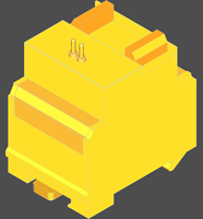
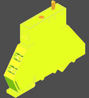
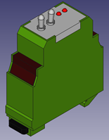
Remote data points Saia PCD® - PCD3.T66x
Remote input/output stations with 4 I/O module slots
BIM - Remote data points
| Tutorial | PCD3.T665 | BIM - Remote data points |
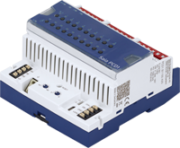
Remote input/output stations with 4 I/O module slots
Smart-RIO, Ether-S-IO data exchange, programmable, 32 KByte program memory,
up to 256 I/O, 2 Interrupts, web server
| PDS - xlsx |

|
0.31 MB | Download | ||
| Revit-file - .rfa - Revision: - |
|
.zip | 0.63 MB | Download | |
| CREO-export - .sat |
|
.zip | 0.19 MB | Download | |
| STEP-file - .step |
|
.zip | 0.49 MB | Download | |
| STP-file - .stp |
|
.zip | 0.22 MB | Download | |
| DXF-file - .dxf |
|
.zip | 0.02 MB | Download | |
| IFC-file - .ifc |
|
.zip | 0.40 MB | Download | |
| IGES-file - .iges |
|
.zip | 0.22 MB | Download | |
| IGS-file - .igs |
|
.zip | 0.22 MB | Download | |
| Manual - 26-892 ENG |
|
6.83 MB | Download | ||
| Manual - 26-892 FRA |

|
6.88 MB | Download | ||
| Manual - 26-892 GER |

|
6.83 MB | Download | ||
| Manual - 26-892 ITA |

|
6.87 MB | Download | ||
| RHINO-file - .3dm |
|
.zip | 0.54 MB | Download | |
| X3D-file - .x3d |
|
.zip | 0.11 MB | Download | |
| Leaflet - 35-017 |
|
0.10 MB | Download |
BIM - Remote data points
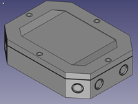
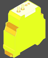
| Tutorial | PCD3.T666 | BIM - Remote data points |
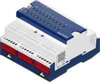
Remote input/output stations with 4 I/O module slots
Smart-RIO, Ether-S-IO data exchange, programmable, 128 KByte program memory,
up to 256 I/O, 2 Interrupts, web server and on-board RS-485 interface
| PDS - xlsx |
|
0.31 MB | Download | ||
| Revit-file - .rfa - Revision: - |
|
.zip | 0.35 MB | Download | |
| CREO-export - .sat |
|
.zip | 0.19 MB | Download | |
| STP-file - .step |
|
.zip | 0.22 MB | Download | |
| STP-file - .stp |
|
.zip | 0.22 MB | Download | |
| DXF-file - .dxf |
|
.zip | 0.16 MB | Download | |
| IFC-file - .ifc |
|
.zip | 0.41 MB | Download | |
| IGES-file - .iges |
|
.zip | 0.22 MB | Download | |
| IGS-file - .igs |
|
.zip | 0.22 MB | Download | |
| Manual - 26-892 ENG |
|
6.83 MB | Download | ||
| Manual - 26-892 FRA |
|
6.88 MB | Download | ||
| Manual - 26-892 GER |
|
6.83 MB | Download | ||
| Manual - 26-892 ITA |
|
6.87 MB | Download | ||
| RHINO-file - .3dm |
|
.zip | 0.54 MB | Download | |
| X3D-file - .x3d |
|
.zip | 0.10 MB | Download | |
| Leaflet - 35-017 |
|
0.10 MB | Download |
BIM - Remote data points
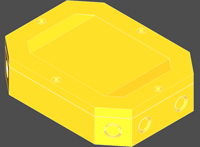
| Tutorial | PCD3.T668 | BIM - Remote data points |
Remote input/output stations with 4 I/O module slots
Smart-RIO for Standby processor unit, Ether-S-IO data exchange, programmable,
128 KByte program memory, up to 256 I/O, 2 Interrupts, web server and on-board RS-485 interface
| PDS - xlsx |
|
0.31 MB | Download | ||
| Revit-file - .rfa - Revision: - |
|
.zip | 0.35 MB | Download | |
| CREO-export - .sat |
|
.zip | 0.20 MB | Download | |
| STEP-file - .step |
|
.zip | 0.50 MB | Download | |
| STP-file - .stp |
|
.zip | 0.22 MB | Download | |
| DXF-file - .dxf |
|
.zip | 0.16 MB | Download | |
| IFC-file - .ifc |
|
.zip | 0.41 MB | Download | |
| IGES-file - .iges |
|
.zip | 0.23 MB | Download | |
| IGS-file - .igs |
|
.zip | 0.23 MB | Download | |
| DS - PP34-006 ENG |
|
1.51 MB | Download | ||
| DS - PP34-006 FRA |
|
1.52 MB | Download | ||
| DS - PP34-006 GER |
|
1.54 MB | Download | ||
| DS - PP34-006 ITA |
|
1.52 MB | Download | ||
| RHINO-file - .3dm |
|
.zip | 0.55 MB | Download | |
| X3D-file - .x3d |
|
.zip | 0.11 MB | Download | |
| Leaflet - 35-017 |
|
0.10 MB | Download | ||
| Manual: 27-645_ENG03 |
|
6.04 MB | Download |
E-Line: S-Serie
BIM - PCD1.A1000-A20
| Tutorial | E-Line - S-Serie | BIM - PCD1.A1000-A20 |
E-Line S-Serie digital output module
Manual override operating level for all outputs
Status LED for outputs
Supply 24 VDC
- 10 digital outputs 24 VDC (12…32 VDC/0.5 A)
- 1 interface RS-485 (S-Bus and Modbus)
- 1 USB service interface
| PDS - xlsx |
|
0.31 MB | Download | ||
| Revit-file - .rfa - Version: a |
|
.zip | 0.29 MB | Download | |
| CREO-export - .sat |
|
.zip | 0.02 MB | Download | |
| Step-file - .step |
|
.zip | 0.02 MB | Download | |
| Step-file - .stp |
|
.zip | 0.02 MB | Download |
BIM - PCD1.A2000-A20
| Tutorial | E-Line - S-Serie | BIM - PCD1.A2000-A20 |
E-Line S-Serie digital output module
manual override operating level for all outputs
status LED for outputs
supply 24 VDC
- 6 relay normally open 230 VAC / 30 VDC, 16 A (resistive load)
- 1 interface RS-485 (S-Bus and Modbus)
- 1 USB Service interface
| PDS - xlsx |
|
0.31 MB | Download | ||
| Revit-file - .rfa - Version: a |
|
.zip | 0.29 MB | Download | |
| CREO-export - .sat |
|
.zip | 0.02 MB | Download | |
| Step-file - .step |
|
.zip | 0.02 MB | Download | |
| Step-file - .stp |
|
.zip | 0.02 MB | Download |
BIM - PCD1.B1100-A20
| Tutorial | E-Line - S-Serie | BIM - PCD1.B1100-A20 |
E-Line S-Serie Digital input/output module
manual override operating level for all outputs
status LED for inputs and outputs
supply 24 VDC
- 4 digital inputs; 24 VDC (source operation)
- 10 relay (6 normally open/ 4 changeover) 250 VAC / 30 VDC, 5 A (DC1)
- 1 interface RS-485 (S-Bus and Modbus)
- 1 USB Service interface
| PDS - xlsx |
|
0.15 MB | Download | ||
| Revit-file - .rfa - Version: a |
|
.zip | 0.29 MB | Download | |
| CREO-export - .sat |
|
.zip | 0.02 MB | Download | |
| Step-file - .step |
|
.zip | 0.02 MB | Download | |
| Step-file - .stp |
|
.zip | 0.02 MB | Download |
BIM - PCD1.B1120-A20
| Tutorial | E-Line - S-Serie | BIM - PCD1.B1120-A20 |
E-Line S-Serie Digital input/output module
manual override operating level for all outputs
status LED for inputs and outputs
supply 24 VDC
- 16 digital inputs; 24 VDC (source operation)
- 4 relay changeover 250 VAC / 30 VDC, 5 A (DC1)
- 1 interface RS-485 (S-Bus and Modbus)
- 1 USB Service interface
| PDS - xlsx |
|
0.15 MB | Download | ||
| Revit-file - .rfa - Version: a |
|
.zip | 0.43 MB | Download | |
| CREO-export - .sat |
|
.zip | 0.02 MB | Download | |
| Step-file - .step |
|
.zip | 0.02 MB | Download | |
| Step-file - .stp |
|
.zip | 0.02 MB | Download |
BIM - PCD1.B5000-A20
| Tutorial | E-Line - S-Serie | BIM - PCD1.B5000-A20 |
E-Line S-Serie Digital input/output module
manual override operating level for all outputs
status LED for inputs and outputs
supply 24 VDC
- 6 Digital inputs 115…230 VAC
- 3 relay normally open 230 VAC / 30 VDC, 6 A (resistive load)
- 1 interface RS-485 (S-Bus and Modbus)
- 1 USB Service interface
| PDS - xlsx |
|
0.31 MB | Download | ||
| Revit-file - .rfa - Version: a |
|
.zip | 0.43 MB | Download | |
| CREO-export - .sat |
|
.zip | 0.02 MB | Download | |
| Step-file - .step |
|
.zip | 0.02 MB | Download | |
| Step-file - .stp |
|
.zip | 0.02 MB | Download |
BIM - PCD1.B5010-A20
| Tutorial | E-Line - S-Serie | BIM - PCD1.B5010-A20 |
E-Line S-Serie Digital input/output module
manual override operating level for all outputs
status LED for inputs and outputs
supply 24 VDC
- 6 Digital inputs 24 VAC/DC
- 3 relay normally open 230 VAC / 30 VDC, 6 A (resistive load)
- 1 interface RS-485 (S-Bus and Modbus)
- 1 USB Service interface
| PDS - xlsx |
|
0.15 MB | Download | ||
| Revit-file - .rfa - Version: a |
|
.zip | 0.43 MB | Download | |
| CREO-export - .sat |
|
.zip | 0.02 MB | Download | |
| Step-file - .step |
|
.zip | 0.02 MB | Download | |
| Step-file - .stp |
|
.zip | 0.02 MB | Download |
BIM - PCD1.E1000-A10
| Tutorial | E-Line - S-Serie | BIM - PCD1.E1000-A10 |
E-Line S-Serie Digital input module
status LED for inputs
supply 24 VDC
- 12 Digital inputs 24 VDC (source operation)
- 1 interface RS-485 (S-Bus and Modbus)
- 1 USB service interface
| PDS - xlsx |
|
0.31 MB | Download | ||
| Revit-file - .rfa - version: a |
|
.zip | 0.43 MB | Download | |
| CREO-export - .sat |
|
.zip | 0.02 MB | Download | |
| Step-file - .step |
|
.zip | 0.02 MB | Download | |
| Step-file - .stp |
|
.zip | 0.02 MB | Download |
BIM - PCD1.G2000-A20
| Tutorial | E-Line - S-Serie | BIM - PCD1.G2000-A20 |
E-Line S-Serie combined input/output module
manual override operating level for all outputs
status LED for inputs and outputs
supply 24 VDC
- 6 universal digital/analogue inputs
- digital inputs 24 VDC
- analoque inputs 12 bits
0…10 V, Pt/Ni 1000, Ni 1000 L&S, NTC,
0…2500 Ohm, 0…7500 Ohm, 0…300 kOhm
- 2 analogue outputs 10 bits, 0…10 V
- 2 triac outputs 24 VAC/1 A or 230 VAC/1 A
- 1 interface RS-485 (S-Bus and Modbus)
- 1 USB Service interface
| PDS - xlsx |
|
0.31 MB | Download | ||
| Revit-file - .rfa - Version: A |
|
.zip | 0.30 MB | Download | |
| CREO-export - .sat |
|
.zip | 0.02 MB | Download | |
| Step-file - .step |
|
.zip | 0.02 MB | Download | |
| Step-file - .stp |
|
.zip | 0.02 MB | Download |
BIM - PCD1.G2100-A10
| Tutorial | E-Line - S-Serie | BIM - PCD1.G2100-A10 |
E-Line S-Serie combined input/output module
manual override operating level for all outputs
status LED for inputs and outputs
supply 24 VDC
- 8 universal digital/analogue inputs
- digital inputs 24 VDC
- analoque inputs 12 bits
0…10 V, Pt/Ni 1000, Ni 1000 L&S, NTC,
0…2500 Ohm, 0…7500 Ohm, 0…300 kOhm
- 1 interface RS-485 (S-Bus and Modbus)
- 1 USB Service interface
| PDS - xlsx |
|
0.15 MB | Download | ||
| Revit-file - .rfa - Version: a |
|
.zip | 0.43 MB | Download | |
| CREO-export - .sat |
|
.zip | 0.02 MB | Download | |
| Step-file - .step |
|
.zip | 0.02 MB | Download | |
| Step-file - .stp |

|
.zip | 0.02 MB | Download |
BIM - PCD1.G2200-A20
| Tutorial | E-Line - S-Serie | BIM - PCD1.G2200-A20 |
E-Line S-Serie combined input/output module
manual override operating level for all outputs
status LED for inputs and outputs
supply 24 VDC
- 8 universal digital/analogue inputs
- digital inputs 24 VDC
- analoque inputs 12 bits
0…10 V, Pt/Ni 1000, Ni 1000 L&S, NTC,
0…2500 Ohm, 0…7500 Ohm, 0…300 kOhm
- 4 analogue outputs 10 bits, 0…10 V
- 1 interface RS-485 (S-Bus and Modbus)
- 1 USB Service interface
| PDS - xlsx |
|
0.31 MB | Download | ||
| Revit-file - .rfa - Version: a |
|
.zip | 0.43 MB | Download | |
| CREO-export - .sat |
|
.zip | 0.02 MB | Download | |
| Step-file - .step |
|
.zip | 0.02 MB | Download | |
| Step-file - .stp |
|
.zip | 0.02 MB | Download | |
| DXG-file - .dxf |
|
.zip | 0.01 MB | Download | |
| IFC-file - .ifc |
|
.zip | 0.02 MB | Download | |
| IGES-file - .iges |
|
.zip | 0.02 MB | Download | |
| IGES-file - .igs |
|
.zip | 0.02 MB | Download | |
| RHINO-file - .3dm |
|
.zip | 0.04 MB | Download | |
| X3D-file - .x3d |
|
.zip | 0.01 MB | Download | |
| DS - 31-151 - ENG |
|
1.58 MB | Download | ||
| DS - 31-151 - FRA |
|
1.61 MB | Download | ||
| DS - 31-151 - GER |
|
1.87 MB | Download | ||
| DS - 31-151 - ITA |
|
1.86 MB | Download |
BIM - PCD1.W5200-A20
| Tutorial | E-Line - S-Serie | BIM - PCD1.W5200-A20 |
E-Line S-Serie analogue output module
manual override operating level for all outputs
status LED for outputs
supply 24 VDC
- 8 analogue outputs 10 bits, 0…10 V
- 1 interface RS-485 (S-Bus and Modbus)
- 1 USB service interface
| PDS - xlsx |
|
0.31 MB | Download | ||
| Revit-file - .rfa - Version: a |
|
.zip | 0.43 MB | Download | |
| CREO-export - .sat |
|
.zip | 0.02 MB | Download | |
| Step-file - .step |
|
.zip | 0.02 MB | Download | |
| Step-file - .stp |
|
.zip | 0.02 MB | Download |
E-Line: L-Serie

BIM - PCD1.B1000-A20
| Tutorial | E-Line - L-Serie | BIM - PCD1.B1000-A20 |
E-Line digital input/output module
manual override operating level for all outputs
status LED for inputs and outputs
supply 24 VDC
- 4 digital inputs 24 VDC (source operation)
- 6 relay normally open 230 VAC / 30 VDC, 4 A (resistive load)
- 4 relay changeover 230 VAC / 30 VDC, 4 A (resistive load)
- 1 interface RS-485 (S-Bus and Modbus)
| PDS - xlsx |
|
0.31 MB | Download | ||
| Revit-file - .rfa - Version: - |
|
.zip | 0.28 MB | Download | |
| CREO-export - .sat |
|
.zip | 0.01 MB | Download | |
| Step-file - .step |
|
.zip | 0.01 MB | Download | |
| Step-file - .stp |
|
.zip | 0.01 MB | Download |
BIM - PCD1.B1010-A20
| Tutorial | E-Line - L-Serie | BIM - PCD1.B1010-A20 |
E-Line digital input/output module
manual override operating level for all outputs
status LED for inputs and outputs
supply 24 VDC
- 24 digital inputs 24 VDC (source operation)
- 6 relay normally open 230 VAC / 30 VDC, 4 A (resistive load)
- 4 relay changeover 230 VAC / 30 VDC, 4 A (resistive load)
- 1 interface RS-485 (S-Bus and Modbus)
| PDS - xlsx |
|
0.31 MB | Download | ||
| Revit-file - .rfa - Version: - |
|
.zip | 0.28 MB | Download | |
| CREO-export - .sat |
|
.zip | 0.01 MB | Download | |
| Step-file - .step |
|
.zip | 0.01 MB | Download | |
| Step-file - .stp |
|
.zip | 0.01 MB | Download |
BIM - PCD1.B1020-A20
| Tutorial | E-Line - L-Serie | BIM - PCD1.B1020-A20 |
E-Line digital input/output module
manual override operating level for all outputs
status LED for inputs and outputs
supply 24 VDC
- 16 digital inputs 24 VDC (source operation)
- 4 relay changeover 230 VAC / 30 VDC, 4 A (resistive load)
- 1 interface RS-485 (S-Bus and Modbus)
| PDS - xlsx |
|
0.31 MB | Download | ||
| Revit-file - .rfa - Version: - |
|
.zip | 0.28 MB | Download | |
| CREO-export - .sat |
|
.zip | 0.01 MB | Download | |
| Step-file - .step |
|
.zip | 0.01 MB | Download | |
| Step-file - .stp |
|
.zip | 0.01 MB | Download |
BIM - PCD1.G5000-A20
| Tutorial | E-Line - L-Serie | BIM - PCD1.G5000-A20 |
E-Line combined input/output module
manual override operating level for all outputs
status LED for inputs and outputs
supply 24 VDC
- 16 digital inputs 24 VDC (source operation)
- 4 relay normally open 230 VAC / 30 VDC, 4 A (resistive load)
- 4 relay changeover 230 VAC / 30 VDC, 4 A (resistive load)
- 8 analogue inputs 12 bits
0…10 V, Pt/Ni 1000, Ni 1000 L&S, NTC, 0…2500 Ohm, 0…7500 Ohm, 0…300 kOhm
- 4 analogue outputs 10 bits, 0…10 V (10 mA max.)
- 1 interface RS-485 (S-Bus and Modbus)
| PDS - xlsx |
|
0.31 MB | Download | ||
| Revit-file - .rfa - Version: - |
|
.zip | 0.29 MB | Download | |
| CREO-export - .sat |
|
.zip | 0.01 MB | Download | |
| Step-file - .step |
|
.zip | 0.01 MB | Download | |
| Step-file - .stp |
|
.zip | 0.01 MB | Download |
BIM - PCD1.G5010-A20
| Tutorial | E-Line - L-Serie | BIM - PCD1.G5010-A20 |
E-Line combined input/output module
manual override operating level for all outputs
status LED for inputs and outputs
supply 24 VDC
- 12 digital inputs 24 VDC (source operation)
- 4 relay changeover 230 VAC / 30 VDC, 4 A (resistive load)
- 12 analogue inputs 12 bits
0…10 V, Pt/Ni 1000, Ni 1000 L&S, NTC, 0…2500 Ohm, 0…7500 Ohm, 0…300 kOhm
- 8 analogue outputs 10 bits, 0…10 V (10 mA max.)
- 1 interface RS-485 (S-Bus and Modbus)
| PDS - xlsx |
|
0.31 MB | Download | ||
| Revit-file - .rfa - Version: - |
|
.zip | 0.28 MB | Download | |
| CREO-export - .sat |
|
.zip | 0.01 MB | Download | |
| Step-file - .step |
|
.zip | 0.01 MB | Download | |
| Step-file - .stp |
|
.zip | 0.01 MB | Download |
BIM - PCD1.G5020-A20
| Tutorial | E-Line - L-Serie | BIM - PCD1.G5020-A20 |
E-Line combined input/output module
manual override operating level for all outputs
status LED for inputs and outputs
supply 24 VDC
- 8 digital inputs 24 VDC (source operation)
- 4 relay changeover 230 VAC / 30 VDC, 4 A (resistive load)
- 16 analogue inputs 12 bits
0…10 V, Pt/Ni 1000, Ni 1000 L&S, NTC, 0…2500 Ohm, 0…7500 Ohm, 0…300 kOhm
- 4 analogue outputs 10 bits, 0…10 V (10 mA max.)
- 1 interface RS-485 (S-Bus and Modbus)
| PDS - xlsx |
|
0.31 MB | Download | ||
| Revit-file - .rfa - Version: - |
|
.zip | 0.29 MB | Download | |
| CREO-export - .sat |
|
.zip | 0.01 MB | Download | |
| Step-file - .step |
|
.zip | 0.01 MB | Download | |
| Step-file - .stp |
|
.zip | 0.01 MB | Download |
E-Line: programmable modules
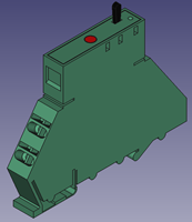
BIM - E-Line room control module
| Tutorial | PCD1.G3600-C15 | BIM - E-Line room control module |
Programmable E-Line input/output module
for room automation
supply 24 VAC/VDC
- 8 digital inputs 24 VAC/VDC
- 3 relay changeover 230 VAC / 30 VDC, 6 A, max. inrush current 15 A
- 1 relay changeover 230 VAC / 30 VDC, 10 A, max. inrush current 65 A
- 4 triac outputs 24 VCA/1A or 230 VAC/1 A
- 4 analogue inputs 12 bits
0…10 V, ±10 V, 0(4)…20 mA, Pt/Ni 1000, NTC, 0…2500 Ohm, 0…7500 Ohm, 0…300 kOhm
- 4 analogue outputs 12 bits, 0…10 V (3 mA max.)
- 3 interfaces: RS-485 (S-Bus), USB & NFC (service)
| PDS - xlsx |
|
|
0.31 MB | Download | |
| Revit-file - .rfa - Version: - |
|
|
.zip | 0.29 MB | Download |
| CREO-export - .sat |
|
|
.zip | 0.01 MB | Download |
| Step-file - .step |
|
|
.zip | 0.01 MB | Download |
| Step-file - .stp |
|
|
.zip | 0.01 MB | Download |
BIM - E-Line room control module
| Tutorial | PCD1.G3601-C15 | BIM - E-Line room control module |
Programmable E-Line input/output module for room automation with auxiliary RS-485 interface
supply 24 VAC/VDC
- 8 digital inputs 24 VAC/VDC
- 3 relay changeover 230 VAC / 30 VDC, 6 A, max. inrush current 15 A
- 1 relay changeover 230 VAC / 30 VDC, 10 A, max. inrush current 65 A
- 4 triac outputs 24 VCA/1A or 230 VAC/1 A
- 4 analogue inputs 12 bits
0…10 V, ±10 V, 0(4)…20 mA, Pt/Ni 1000, NTC, 0…2500 Ohm, 0…7500 Ohm, 0…300 kOhm
- 4 analogue outputs 12 bits, 0…10 V (3 mA max.)
- 4 interfaces: RS-485 (S-Bus), auxiliary RS-485, USB & NFC (service)
| PDS - xlsx |
|
|
0.31 MB | Download | |
| Revit-file - .rfa - Version: - |
|
|
.RFA | 0.32 MB | Download |
| CREO-export - .sat |
|
|
.zip | 0.01 MB | Download |
| Step-file - .step |
|
|
.zip | 0.01 MB | Download |
| Step-file - .stp |
|
|
.zip | 0.01 MB | Download |
Remote data points Saia PCD®
Remote input/output modules with serial S-Bus interface - type RAIL (top-hat rail mounting)
BIM - Remote data points Saia PCD®: PCD7.L100
| Tutorial | PCD7.L100 | BIM - Remote data points Saia PCD®: PCD7.L100 |
Remote input/output modules with serial S-Bus interface - type RAIL (top-hat rail mounting)
Digital input module:
- 4 inputs 24 VDC/VAC, with local override functionality
| Revit-file - .rfa - Revision: - |
|
|
Download | ||
| CREO-export - .sat |
|
.zip | 0.03 MB | Download | |
| STEP-file - .step |
|
.zip | 0.07 MB | Download | |
| STP-file - .stp |
|
.zip | 0.03 MB | Download | |
| DXF-file - .dxf |
|
.zip | 0.06 MB | Download | |
| IFC-file - .ifc |
|
.zip | 0.14 MB | Download | |
| IGES-file - .iges |
|
.zip | 0.03 MB | Download | |
| IGS-file - .igs |
|
.zip | 0.03 MB | Download | |
| RHINO-file - .3dm |
|
.zip | 0.13 MB | Download | |
| X3D-file - .x3d |
|
.zip | 0.03 MB | Download | |
| Leaflet - 26-000 ENG |
|
0.17 MB | Download | ||
| Leaflet - 26-000 GER |
|
0.16 MB | Download | ||
| TI - 26-339 ENG |
|
6.22 MB | Download | ||
| TI - 26-339 FRA |
|
2.02 MB | Download | ||
| TI - 26-339 GER |
|
6.24 MB | Download | ||
| TI - 26-339 ITA |
|
6.26 MB | Download | ||
| TI - 26-339 SWE |

|
6.23 MB | Download | ||
| Leaflet - 26-000 bilingual |
|
0.33 MB | Download |
BIM - Remote data points Saia PCD®: PCD7.L110
| Tutorial | PCD7.L110 | BIM - Remote data points Saia PCD®: PCD7.L110 |
Remote input/output modules with serial S-Bus interface - type RAIL (top-hat rail mounting)
Digital input module:
- 4 inputs 24 VDC/VAC, without local override functionality
| Revit-file - .rfa - Revision: - |
|
|
Download | ||
| CREO-export - .sat |
|
.zip | 0.02 MB | Download | |
| STEP-file - .step |
|
.zip | 0.06 MB | Download | |
| STP-file - .stp |
|
.zip | 0.02 MB | Download | |
| DXF-file - .dxf |
|
.zip | 0.01 MB | Download | |
| IFC-file - .ifc |
|
.zip | 0.02 MB | Download | |
| IGES-file - .iges |
|
.zip | 0.03 MB | Download | |
| IGS-file - .igs |
|
.zip | 0.03 MB | Download | |
| RHINO-file - .3dm |
|
.zip | 0.06 MB | Download | |
| X3D-file - .x3d |
|
.zip | 0.00 MB | Download | |
| Leaflet - 26-002 ENG |
|
0.20 MB | Download | ||
| Leaflet - 26-002 GER |
|
0.10 MB | Download | ||
| TI - 26-339 ENG |
|
6.22 MB | Download | ||
| TI - 26-339 FRA |
|
2.02 MB | Download | ||
| TI - 26-339 GER |
|
6.24 MB | Download | ||
| TI - 26-339 ITA |
|
6.26 MB | Download | ||
| TI - 26-339 SWE |
|
6.23 MB | Download | ||
| Leaflet - 26-002 bilingual |
|
0.30 MB | Download |
BIM - Remote input/output modules type: RAIL
| Tutorial | PCD7.L120 | BIM - Remote input/output modules type: RAIL |
Digital remote input/output modules with serial S-Bus interface - type RAIL (top-hat rail mounting)
- 4 inputs 24 VDC/VAC and
- 2 relay outputs 250 VAC, with local override and
- integrated light & sunblind functionality
| Revit-file - .rfa - Revision: - |
|
|
Download | ||
| CREO-export - .sat |
|
.zip | 0.03 MB | Download | |
| STEP-file - .step |
|
.zip | 0.06 MB | Download | |
| STP-file - .stp |
|
.zip | 0.03 MB | Download | |
| DXF-file - .dxf |
|
.zip | 0.03 MB | Download | |
| IFC-file - .ifc |
|
.zip | 0.08 MB | Download | |
| IGES-file - .iges |
|
.zip | 0.03 MB | Download | |
| IGS-file - .igs |
|
.zip | 0.03 MB | Download | |
| RHINO-file - .3dm |
|
.zip | 0.10 MB | Download | |
| X3D-file - .x3d |
|
.zip | 0.02 MB | Download | |
| TI - 26-339 ENG |
|
6.22 MB | Download | ||
| TI - 26-339 FRA |
|
2.02 MB | Download | ||
| TI - 26-339 GER |
|
6.24 MB | Download | ||
| TI - 26-339 ITA |
|
6.26 MB | Download | ||
| TI - 26-339 SWE |
|
6.23 MB | Download | ||
| Leaflet - 26-003 XXX - up-to-FW310 |
|
0.25 MB | Download | ||
| Leaflet - 26-004 ENG - starting with FW310 |
|
0.33 MB | Download | ||
| Leaflet - 26-004 GER - starting with FW310 |
|
0.31 MB | Download |
BIM - Remote data points Saia PCD®: PCD7.L130
| Tutorial | PCD7.L130 | BIM - Remote data points Saia PCD®: PCD7.L130 |
Remote input/output modules with serial S-Bus interface - type RAIL (top-hat rail mounting)
Digital input module:
- 10 inputs 24 VDC/VAC
| Revit-file - .rfa - Revision: - |
|
|
Download | ||
| CREO-export - .sat |
|
|
.zip | 0.02 MB | Download |
| Step-file - .step |
|
|
.zip | 0.06 MB | Download |
| Step-file - .stp |
|
|
.zip | 0.02 MB | Download |
| DXF-file - .dxf |
|
|
.zip | 0.01 MB | Download |
| IFC-file - .ifc |
|
|
.zip | 0.02 MB | Download |
| IGES-file - .iges |
|
|
.zip | 0.03 MB | Download |
| IGS-file - .igs |
|
|
.zip | 0.03 MB | Download |
| RHINO-file - .3dm |
|
|
.zip | 0.05 MB | Download |
| X3D-file - .x3d |
|
|
.zip | 0.00 MB | Download |
| TI - 26-339 ENG |
|
|
6.22 MB | Download | |
| TI - 26-339 FRA |
|
|
2.02 MB | Download | |
| TI - 26-339 GER |
|
|
6.24 MB | Download | |
| TI - 26-339 ITA |
|
|
6.26 MB | Download | |
| TI - 26-339 SWE |
|
|
6.23 MB | Download | |
| Leaflet - 26-007 ENG |
|
|
0.16 MB | Download | |
| Leaflet - 26-007 GER |
|
|
0.14 MB | Download |
BIM - Remote data points Saia PCD®: PCD7.L200
| Tutorial | PCD7.L200 | BIM - Remote data points Saia PCD®: PCD7.L200 |
Remote input/output modules with serial S-Bus interface - type RAIL (top-hat rail mounting)
Digital output module:
- 4 relays 250 VAC/6 A, with local override functionality
| Revit-file - .rfa - Revision: - |
|
|
Download | ||
| CREO-export - .sat |
|
.zip | 0.03 MB | Download | |
| STEP-file - .step |
|
.zip | 0.07 MB | Download | |
| STP-file - .stp |
|
.zip | 0.03 MB | Download | |
| DXF-file - .dxf |
|
.zip | 0.06 MB | Download | |
| IFC-file - .ifc |
|
.zip | 0.14 MB | Download | |
| IGES-file - .iges |
|
.zip | 0.03 MB | Download | |
| IGS-file - .igs |
|
.zip | 0.03 MB | Download | |
| RHINO-file - .3dm |
|
.zip | 0.13 MB | Download | |
| X3D-file - .x3d |
|
.zip | 0.04 MB | Download | |
| Leaflet - 26-008 ENG |
|
0.19 MB | Download | ||
| Leaflet - 26-008 GER |
|
0.18 MB | Download | ||
| TI - 26-339 ENG |
|
6.22 MB | Download | ||
| TI - 26-339 FRA |
|
2.02 MB | Download | ||
| TI - 26-339 GER |
|
6.24 MB | Download | ||
| TI - 26-339 ITA |
|
6.26 MB | Download | ||
| TI - 26-339 SWE |
|
6.23 MB | Download | ||
| Leaflet - 26-008 bilingual |
|
0.37 MB | Download |
BIM - Remote data points Saia PCD®: PCD7.L210
| Tutorial | PCD7.L210 | BIM - Remote data points Saia PCD®: PCD7.L210 |
Remote input/output modules with serial S-Bus interface - type RAIL (top-hat rail mounting)
Digital output module:
- 4 triac 24…250 VAC/0.8 A, with local override functionality
| PDS - xlsx |
|
|
Download | ||
| Revit-file - .rfa - Revision: - |
|
|
Download | ||
| CREO-export - .sat |
|
|
Download | ||
| Step-file - .step |
|
.zip | 0.07 MB | Download | |
| Step-file - .stp |
|
.zip | 0.07 MB | Download | |
| DXG-file - .dxf |
|
|
Download | ||
| IFC-file - .ifc |
|
.zip | 0.09 MB | Download | |
| IGES-file - .iges |
|
.zip | 0.03 MB | Download | |
| STL-file - .stl |
|
.zip | 0.16 MB | Download | |
| TI - 26-339 ENG |
|
6.22 MB | Download | ||
| TI - 26-339 FRA |
|
2.02 MB | Download | ||
| TI - 26-339 GER |
|
6.24 MB | Download | ||
| TI - 26-339 ITA |
|
6.26 MB | Download | ||
| Leaflet - 26-022 ENG |
|
0.26 MB | Download | ||
| Leaflet - 26-022 GER |
|
0.26 MB | Download |
BIM - Remote input/output modules type: RAIL
| Tutorial | PCD7.L300 | BIM - Remote input/output modules type: RAIL |
Remote input/output modules with serial S-Bus interface - type RAIL (top-hat rail mounting)
Analogue input module, 4 channels each of Pt 1000 and 0…10 VDC
| Revit-file - .rfa - Revision: - |
|
|
Download | ||
| CREO-export - .sat |
|
|
.zip | 0.02 MB | Download |
| STEP-file - .step |
|
|
.zip | 0.06 MB | Download |
| STP-file - .stp |
|
|
.zip | 0.06 MB | Download |
| DXF-file - .dxf |
|
|
.zip | 0.01 MB | Download |
| IFC-file - .ifc |
|
|
.zip | 0.02 MB | Download |
| IGES-file - .iges |
|
|
.zip | 0.03 MB | Download |
| IGS-file - .igs |
|
|
.zip | 0.03 MB | Download |
| RHINO-file - .3dm |
|
|
.zip | 0.05 MB | Download |
| X3D-file - .x3d |
|
|
.zip | 0.00 MB | Download |
| TI - 26-339 ENG |
|
|
6.22 MB | Download | |
| TI - 26-339 FRA |
|
|
2.02 MB | Download | |
| TI - 26-339 GER |
|
|
6.24 MB | Download | |
| TI - 26-339 ITA |
|
|
6.26 MB | Download | |
| TI - 26-339 SWE |
|
|
6.23 MB | Download | |
| Leaflet - 26-023 ENG |
|
|
0.26 MB | Download | |
| Leaflet - 26-023 GER |
|
|
0.26 MB | Download |
BIM - Remote data points Saia PCD®: PCD7.L310
| Tutorial | PCD7.L310 | BIM - Remote data points Saia PCD®: PCD7.L310 |
Remote input/output modules with serial S-Bus interface - type RAIL (top-hat rail mounting)
Digital input module:
- 4 inputs Ni1000 and 0...10 VDC
| Revit-file - .rfa - Revision: - |
|
|
Download | ||
| CREO-export - .sat |
|
|
.zip | 0.02 MB | Download |
| Step-file - .step |
|
|
.zip | 0.06 MB | Download |
| STP-file - .stp |
|
|
.zip | 0.02 MB | Download |
| DXF-file - .dxf |
|
|
.zip | 0.01 MB | Download |
| IFC-file - .ifc |
|
|
.zip | 0.02 MB | Download |
| IGES-file - .iges |
|
|
.zip | 0.03 MB | Download |
| IGS-file - .igs |
|
|
.zip | 0.03 MB | Download |
| RHINO-file - .3dm |
|
|
.zip | 0.05 MB | Download |
| X3D-file - .x3d |
|
|
.zip | 0.00 MB | Download |
| TI - 26-339 ENG |
|
|
6.22 MB | Download | |
| TI - 26-339 FRA |
|
|
2.02 MB | Download | |
| TI - 26-339 GER |
|
|
6.24 MB | Download | |
| TI - 26-339 ITA |
|
|
6.26 MB | Download | |
| TI - 26-339 SWE |
|
|
6.23 MB | Download | |
| Leaflet - 26-025 ENG |
|
|
0.26 MB | Download | |
| Leaflet - 26-025 GER |
|
|
0.26 MB | Download | |
| Leaflet - 26-025 XXX - bilingual |
|
|
0.46 MB | Download |
BIM - Remote input/output modules type: RAIL
| Tutorial | PCD7.L320 | BIM - Remote input/output modules type: RAIL |
Remote input/output modules with serial S-Bus interface - type RAIL (top-hat rail mounting)
Analogue input module with 8 universally configurable channels for
- 0 ... 10 VDC or
- various passive and active temperature sensors such as
Pt 1000, Ni 1000, NTC 10K and 10 additional temperature sensor characteristics
| Revit-file - .rfa - Revision: - |
|
|
Download | ||
| CREO-export - .sat |
|
.zip | 0.02 MB | Download | |
| STEP-file - .step |
|
.zip | 0.06 MB | Download | |
| STP-file - .stp |
|
.zip | 0.02 MB | Download | |
| DXF-file - .dxf |
|
.zip | 0.01 MB | Download | |
| IFC-file - .ifc |
|
.zip | 0.02 MB | Download | |
| IGES-file - .iges |
|
.zip | 0.03 MB | Download | |
| IGS-file - .igs |
|
.zip | 0.03 MB | Download | |
| RHINO-file - .3dm |
|
.zip | 0.06 MB | Download | |
| X3D-file - .x3d |
|
.zip | 0.00 MB | Download | |
| TI - 26-339 ENG |
|
6.22 MB | Download | ||
| TI - 26-339 FRA |
|
2.02 MB | Download | ||
| TI - 26-339 GER |
|
6.24 MB | Download | ||
| TI - 26-339 ITA |
|
6.26 MB | Download | ||
| TI - 26-339 SWE |
|
6.23 MB | Download | ||
| Leaflet - 26-020 ENG |
|
1.12 MB | Download | ||
| Leaflet - 26-020 GER |
|
1.13 MB | Download |
BIM - Remote data points Saia PCD®: PCD7.L500
| Tutorial | PCD7.L500 | BIM - Remote data points Saia PCD®: PCD7.L500 |
Power supply module 230 VAC / 24 VDC (DIN rail mounting)
Power supply 230 VAC / 24 VDC
for supply of all RAIL and SAFE modules,
- input 110…240 VAC,
- output 24 VDC / 700 mA,
- for max. 15 RAIL or SAVE modules
| Revit-file - .rfa - Revision: - |
|
|
Download | ||
| CREO-export - .sat |
|
.zip | 0.02 MB | Download | |
| STEP-file - .step |
|
.zip | 0.06 MB | Download | |
| STP-file - .stp |
|
.zip | 0.02 MB | Download | |
| DXF-file - .dxf |
|
.zip | 0.01 MB | Download | |
| IFC-file - .ifc |
|
.zip | 0.02 MB | Download | |
| IGES-file - .iges |
|
.zip | 0.03 MB | Download | |
| IGS-file - .igs |
|
.zip | 0.03 MB | Download | |
| RHINO-file - .3dm |
|
.zip | 0.06 MB | Download | |
| X3D-file - .x3d |
|
.zip | 0.00 MB | Download | |
| Leaflet - 26-027 ENG - old types, up to 500 mA |
|
0.10 MB | Download | ||
| Leaflet - 26-027 GER - old types, up to 500 mA |
|
0.11 MB | Download | ||
| Leaflet - 26-036 GER - new types, up to 700 mA |
|
0.39 MB | Download | ||
| Leaflet - 26-036 GER - old types, up to 500 mA |
|
0.41 MB | Download | ||
| TI - 26-339 ENG |
|
6.22 MB | Download | ||
| TI - 26-339 FRA |
|
2.02 MB | Download | ||
| TI - 26-339 GER |
|
6.24 MB | Download | ||
| TI - 26-339 ITA |
|
6.26 MB | Download | ||
| TI - 26-339 SWE |
|
6.23 MB | Download |
Remote data points Saia PCD®
Remote input/output modules with serial S-Bus interface - type SAVE (surface mounted)
BIM - Remote input/output modules type: SAFE
| Tutorial | PCD7.L121 | BIM - Remote input/output modules type: SAFE |
Digital remote input/output modules with serial S-Bus interface - type SAVE (surface mounted)
- 4 inputs 24 VDC/VAC and 2 relay outputs 250 VAC,
with local override and integrated
light & sunblind functionality (protection class IP 65)
| Revit-file - .rfa - Revision: - |
|
|
Download | ||
| CREO-export - .sat |
|
.zip | 0.02 MB | Download | |
| STEP-file - .step |
|
.zip | 0.06 MB | Download | |
| STP-file - .stp |
|
.zip | 0.06 MB | Download | |
| DXF-file - .dxf |
|
.zip | 0.07 MB | Download | |
| IFC-file - .ifc |
|
.zip | 0.14 MB | Download | |
| IGES-file - .iges |
|
.zip | 0.03 MB | Download | |
| IGS-file - .igs |
|
.zip | 0.03 MB | Download | |
| RHINO-file - .3dm |
|
.zip | 0.14 MB | Download | |
| X3D-file - .x3d |
|
.zip | 0.05 MB | Download | |
| TI - 26-339 ENG |
|
6.22 MB | Download | ||
| TI - 26-339 FRA |
|
2.02 MB | Download | ||
| TI - 26-339 GER |
|
6.24 MB | Download | ||
| TI - 26-339 ITA |
|
6.26 MB | Download | ||
| TI - 26-339 SWE |
|
6.23 MB | Download | ||
| Leaflet - 26-005 XXX - up-to-FW310 |
|
0.16 MB | Download | ||
| Leaflet - 26-006 ENG - starting-with-FW310 |
|
0.25 MB | Download | ||
| Leaflet - 26-006 GER - starting-with-FW310 |
|
0.32 MB | Download |
Other components for switch cabinet

Coupler modules with local override functionalityl.
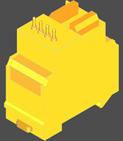
BIM - Changeover switch with local override
| Tutorial | PCD7.L252 | BIM - Changeover switch with local override |
Coupler modules with local override functionality
Changeover switch with local override functionality Auto/On/Off :
1 changeover switch max. 250 VDC/VAC/8 A,
local override, auto acknowledge,
LED indicator, 2 added terminals for jumpers,
11.2 mm overall width, spring terminals
| Revit-file - .rfa - Revision: - |
|
|
Download | ||
| CREO-export - .sat |
|
.zip | 0.05 MB | Download | |
| Step-file - .step |
|
.zip | 0.13 MB | Download | |
| STP-file - .stp |
|
.zip | 0.06 MB | Download | |
| DXF-file - .dxf |
|
.zip | 0.06 MB | Download | |
| IFC-file - .ifc |
|
.zip | 0.15 MB | Download | |
| IGES-file - .iges |
|
.zip | 0.07 MB | Download | |
| IGS-file - .igs |
|
.zip | 0.07 MB | Download | |
| RHINO-file - .3dm |
|
.zip | 0.21 MB | Download | |
| X3D-file - .x3d |
|
.zip | 0.05 MB | Download | |
| Leaflet - 26-041 ENG |
|
1.02 MB | Download | ||
| Leaflet - 26-041 GER |
|
1.05 MB | Download | ||
| Leaflet - 26-041 XXX - bilingual |
|
1.23 MB | Download |
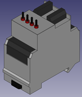
BIM - Changeover switch with local override functionality
| Tutorial | PCD7.L452 | BIM - Changeover switch with local override functionality |
Coupler modules with local override functionality
Changeover switch with local override functionality Auto/On/Off :
Analogue data encoder for local control variables :
local override functionality Auto/On/Off,
potentiometer 0…10 VDC,
local override, auto acknowledge,
LED indicator,
11.2 mm overall width, spring terminals
| PDS - xlsx |
|
|
Download | ||
| Revit-file - .rfa - Revision: - |
|
|
Download | ||
| CREO-export - .sat |
|
.zip | 0.05 MB | Download | |
| STEP-file - .step |
|
.zip | 0.12 MB | Download | |
| STP-file - .stp |
|
.zip | 0.05 MB | Download | |
| DXF-file - .dxf |
|
.zip | 0.06 MB | Download | |
| IFC-file - .ifc |
|
.zip | 0.15 MB | Download | |
| IGES-file - .iges |
|
.zip | 0.06 MB | Download | |
| IGS-file - .igs |
|
.zip | 0.06 MB | Download | |
| RHINO-file - .3dm |
|
.zip | 0.22 MB | Download | |
| X3D-file - .x3d |
|
.zip | 0.05 MB | Download | |
| Leaflet - 26-044 ENG |
|
0.78 MB | Download | ||
| Leaflet - 26-044 GER |
|
0.77 MB | Download | ||
| Leaflet - 26-044 bilingual |
|
1.23 MB | Download |
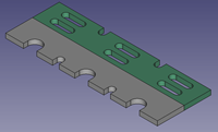
BIM - Labelling plate for PCD7.L252 module
| Tutorial | PCD7.L290 | BIM - Labelling plate for PCD7.L252 module |
Coupler modules with local override functionality
Labelling plate for PCD7.L252 module Price for 10 pieces
| Revit-file - .rfa - Revision: - |
|
|
Download | ||
| CREO-export - .sat |
|
.zip | 0.05 MB | Download | |
| STEP-file - .step |
|
.zip | 0.13 MB | Download | |
| STP-file - .stp |
|
.zip | 0.06 MB | Download | |
| DXF-file - .dxf |
|
.zip | 0.01 MB | Download | |
| IFC-file - .ifc |
|
.zip | 0.03 MB | Download | |
| IGES-file - .iges |
|
.zip | 0.06 MB | Download | |
| IGS-file - .igs |
|
.zip | 0.06 MB | Download | |
| RHINO-file - .3dm |
|
.zip | 0.13 MB | Download | |
| X3D-file - .x3d |
|
.zip | 0.01 MB | Download |
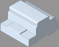
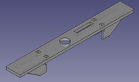
BIM - Jumper for connection of the supply voltage
| Tutorial | PCD7.L291 | BIM - Jumper for connection of the supply voltage |
Coupler modules with local override functionality
Jumper for connection of the supply voltage of up to 10 modules PCD7.L252 and PCD7.L452
| Revit-file - .rfa - Revision: - |
|
.zip | 0.29 MB | Download | |
| CREO-export - .sat |
|
.zip | 0.01 MB | Download | |
| Step-file - .step |
|
.zip | 0.03 MB | Download | |
| Step-file - .stp |
|
.zip | 0.01 MB | Download | |
| DXG-file - .dxf |
|
.zip | 0.01 MB | Download | |
| IFC-file - .ifc |
|
.zip | 0.04 MB | Download | |
| IGES-file - .iges |
|
.zip | 0.02 MB | Download | |
| RHINO-file - .3dm |
|
.zip | 0.04 MB | Download | |
| Leaflet - 26-041 ENG |
|
1.02 MB | Download | ||
| Leaflet - 26-041 GER |
|
1.05 MB | Download | ||
| Leaflet - 26-044 ENG |
|
0.78 MB | Download | ||
| Leaflet - 26-044 GER |
|
0.77 MB | Download |
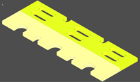
BIM - Labelling plate for PCD7.L452 module
| Tutorial | PCD7.L490 | BIM - Labelling plate for PCD7.L452 module |
Coupler modules with local override functionality
Labelling plate for PCD7.L452 module Price for 10 pieces
| Revit-file - .rfa - Revision: - |
|
|
Download | ||
| CREO-export - .sat |
|
.zip | 0.05 MB | Download | |
| STEP-file - .step |
|
.zip | 0.13 MB | Download | |
| STP-file - .stp |
|
.zip | 0.06 MB | Download | |
| DXF-file - .dxf |
|
.zip | 0.01 MB | Download | |
| IFC-file - .ifc |
|
.zip | 0.03 MB | Download | |
| IGES-file - .iges |
|
.zip | 0.06 MB | Download | |
| IGS-file - .iigs |
|
.zip | 0.06 MB | Download | |
| RHINO-file - .3dm |
|
.zip | 0.13 MB | Download | |
| X3D-file - .x3d |
|
.zip | 0.01 MB | Download |
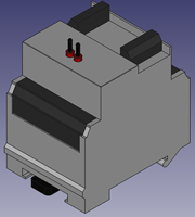
BIM - Coupler module for two-stage motor control
| Tutorial | PCD7.L260 | BIM - Coupler module for two-stage motor control |
Coupler modules with local override functionality
Coupler module for two-stage motor control :
- mutually latched relay 250 VDC/VAC/4 A,
- local override, auto acknowledge,
- LED indicator,
- 22.5 mm overall width,
- screw terminals
| Revit-file - .rfa - Revision: - |
|
|
Download | ||
| CREO-export - .sat |
|
.zip | 0.03 MB | Download | |
| STEP-file - .step |
|
.zip | 0.07 MB | Download | |
| STP-file - .stp |
|
.zip | 0.03 MB | Download | |
| DXF-file - .dxf |
|
.zip | 0.04 MB | Download | |
| IFC-file - .ifc |
|
.zip | 0.10 MB | Download | |
| IGES-file - .iges |
|
.zip | 0.03 MB | Download | |
| IGS-file - .igs |
|
.zip | 0.03 MB | Download | |
| RHINO-file - .3dm |
|
.zip | 0.12 MB | Download | |
| X3D-file - .x3d |
|
.zip | 0.03 MB | Download | |
| Leaflet - 26-042 ENG |
|
1.36 MB | Download | ||
| Leaflet - 26-042 GER |
|
1.29 MB | Download | ||
| Leaflet - 26-042 bilingual |
|
1.46 MB | Download |