272
saia-pcd.com
24
6
9
4
Sample Project
Planning guide
In-/outputs:
connection technology: Spring terminals
(0.5–1.5 mm², rigid or flexible conductor);
plug-in terminals. Module replacement should
be possible with no additional tool required.
4.
Definition of in-/outputs
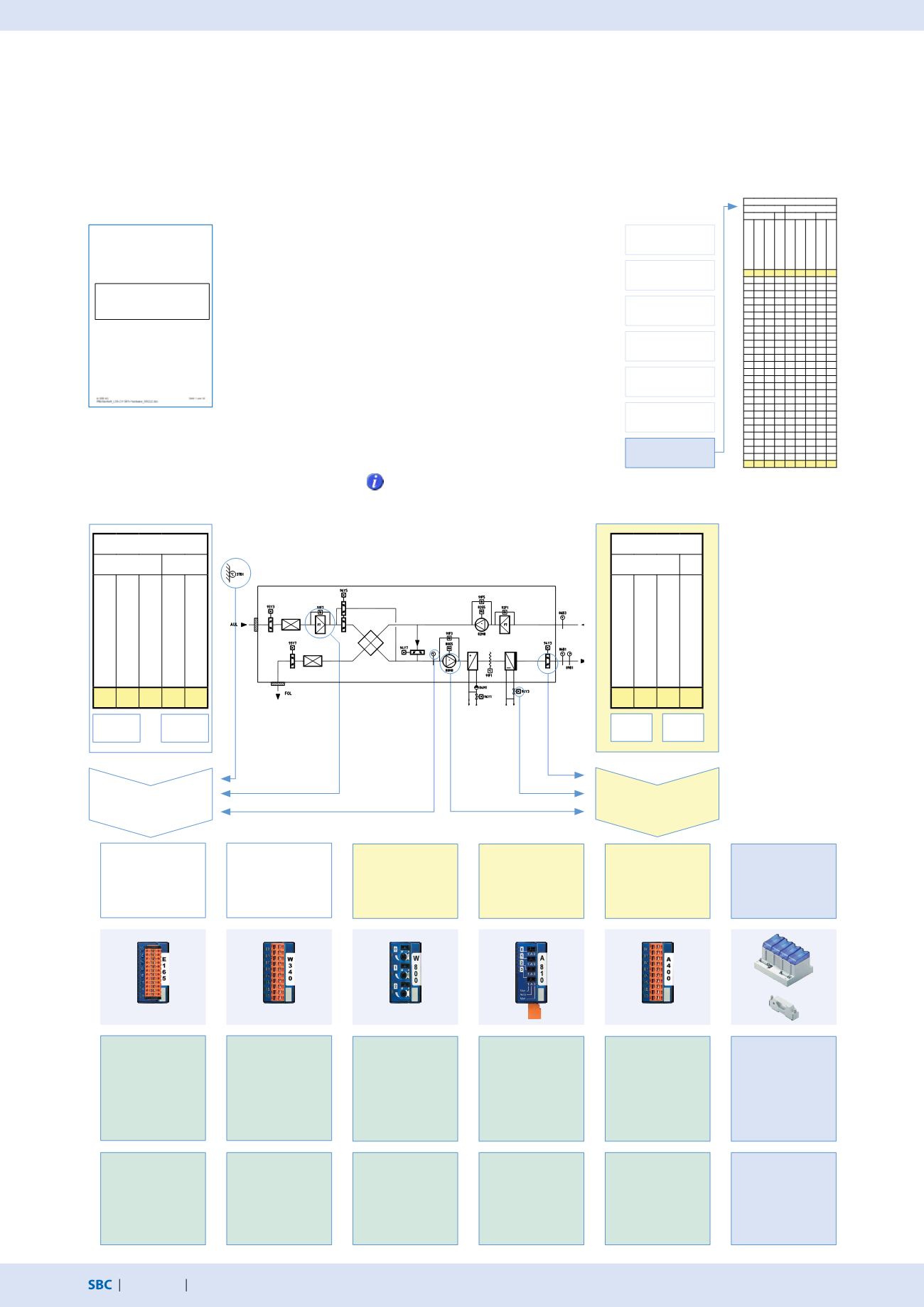
The modular systems can be expanded and adapted to the relevant requirements using various plug-in I/O modules.
The system can therefore be adjusted or expanded at any time.
Inputs
Outputs
Mounting location
Manual operation
Expandability
Communication
Modularity
Data memory
In-/outputs
Requirement arising from the specifications
Selection criteria
Specifications
System concept
Take into account module current
consumption for the 5V bus and the
+V bus. Payload data varies depending
on the in-/output module.
Measurements
active/passive
Switching command
for fans / pumps
Switching command
fire safety /
SUP - EHA dampers
Continuous setting
command hot/cold
water valve
Operating mode/
status/
error messages
PCD3 expansion
Analogue input (AI)
Requirement:
6
Number of modules: 1
Range:
8
Reserves:
2
Binary output (BO)
Requirement: 4v9
Number of modules: 1
Range:
4
Reserves:
0
Binary output (BO)
Requirement: 5v9
Number of modules: 1
Range:
8
Reserves:
3
Analogue output (AO)
Requirement:
4
Number of modules: 1
Range:
4
Reserves:
0
Binary input (BI)
Requirement:
24
Number of modules: 2
Range:
32
Reserves:
8
Number of modules: 1
PCD3.W340
Analogue input
module with
8
in-
puts; Universally
selectable active/
passive
PCD3.A810
Binary output module
230 VAC with
4
relays: output con-
tacts can be
operated manually
PCD3.A400
Binary output
module 24 VDC with
8
transistor output
contacts
PCD3.W800
Analogue output
module with
4
out-
puts 0…10 VDC;
3× can be operated
manually
PCD3.E165
Binary input module
with
16
inputs
24 VDC / feedback
LED
PCD3.C100
Expansion housing 4
slots with PCD3.K010
Inputs
BE
IO
Operating/Status message
Fault/Alarm
Counting
Reading active
Reading passive
8 16 0 0 6
Outputs
BA
AO
Continuous switching
command
Pulse switching command
PWM/3 point setting
command
Continuous setting
command
9 0 0 4
Project:
Control and fault reporting
system Switzerland LSS-CH
PLC automation equipment
Specifications
PhysikalischeE/A-Funktionen
Ausgänge
Eingänge
BA AA BE AE
Dauer-Schaltbefehl
Impuls-Schaltbefehl
PWM/3-Punkt-Stellbefehl
StetigerStellbefehl
Betriebs-/Statusmeldung
Störung/Alarm
Zählen
Messwert aktiv
Messwert passiv
1 2 3 4 5 6 7 8 9
3
2 1
1
1
1
1
1
1
1
1
1
4
1
1
1
1
1
2 1
1
2 1
1
1
1
1
1
4
1
1
1
9 0 0 4 8 16 0 0 6


