269
saia-pcd.com
C
1
Sample Project
Planning guide
2
Product Launch
1
Planning Guide
3
Abbreviations
4
Type Index
The requirements of technical planners must be considered when selecting the appropriate automation products.
The technical specifications for automation equipment in the following “Standard ventilation” example have been used to
select the most suitable Saia PCD® device family. Other factors such as plant operation are covered in separate chapters.
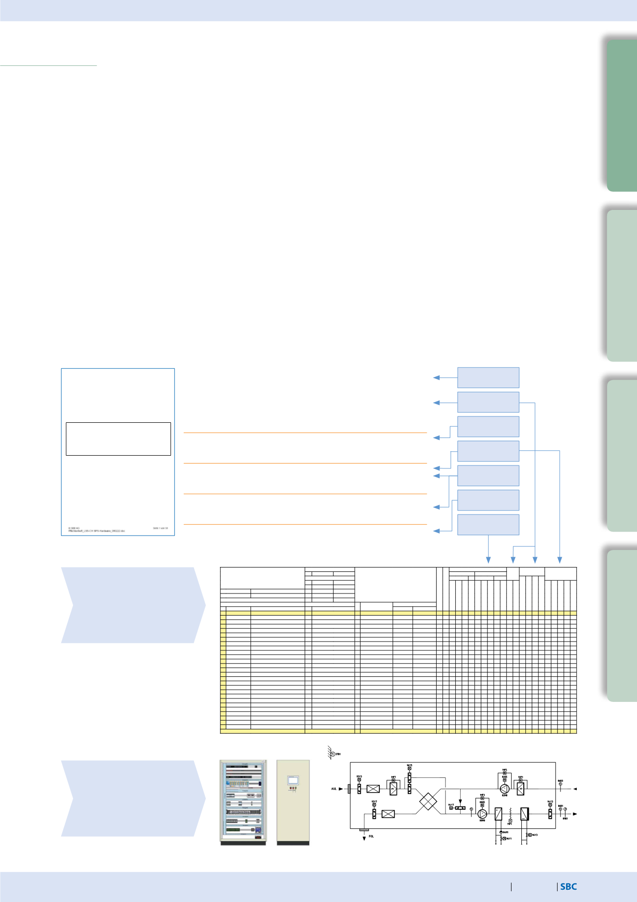
Procedure / work steps
In accordance with the planning fundamentals (specification), the following steps should be taken when choosing
automation products:
1. Examine the specification requirements for automation equipment to define the selection criteria
2. Define the device family based on the required data points / functions
3. Select the products for communication, expandability and flexibility
4. Define input/output modules
5. Composition of equipment
Planning guide
Plant principle
Display of plant for visual data
point assignment
Indication of mounting location
Data point function list
Selection criteria for
– Device family
– Control functions
– Communication/interfaces
Description:
Two-stage partial air conditioning system with plate
heat exchanger, air heater and air cooler.
Ventilation with manual/override function.
A control cabinet should be included to install the
electrical and automation technology.
Controls:
Flexible, modular and expandable controls
Interfaces:
Basic interfaces – Ethernet / USB energy
measurement M-Bus; expandability option
Expansion
min. 20% expansion reserve
reserve:
Data:
Recording/storage of operational data
Specifications
1.
Examine the specification requirements
Requirement arising from the specifications
Selection criteria
In-/outputs
Modularity
Communication
Mounting
location
Manual
operation
Expandability
Data memory
Project:
Control and fault reporting
system Switzerland LSS-CH
PLC automation equipment
Specifications
Erstellt
Allgemeines:
Anschlussleistung (kW)
Hardwarefunktionen
PhysikalischeE/A-Funktionen Not-
bedie-
nung
Bedien-
Funktionen Kommunikative
E/A-Funktionen
Bearb:SP Datum:1.3.11
Ausgänge
Eingänge
Geändert:
BA AA BE AE
Grafik/Anlagenbild
DynamischeEinblendung
Ereignis-Anweisung
NachrichtanexterneStelle
a Bearb:
Datum:
Dauer-Schaltbefehl
Impuls-Schaltbefehl
PWM/3-Punkt-Stellbefehl
StetigerStellbefehl
Betriebs-/Statusmeldung
Störung/Alarm
Zählen
Messwert aktiv
Messwert passiv
Schalten/Stellen
Anzeigen
Schalten
Stellen/Sollwert
Melden
Zählen
Messen
b Bearb:
Datum:
Projekt-Nr 101726 Objekt:ZimmerG530
c Bearb:
Datum:
Anlagen-Nr: LA03 Anlage: LüftungNebenräume
d Bearb:
Datum:
Anlage-Ort:
Aussen, 6.OG
e Bearb:
Datum:
Schaltschrank
SLU01
Typ
Anzahl
Bemerkungen
Feldgeräte
Nr.Adresse
Text
CodBeschreibung
Hersteller
Typ
a
b
c1
c2
d
e
f1
f2
g h 1 2 3 4 5 6 7 8 9 1 2 n1 n2 n3 n4 k1 k2 k3 k4 k5
LA03
Anlagenschalter
a11 Anlageallg.:Auto-Aus-Ein 1
0 3
2 1
1 5 1 1
a21Brandalarm
1
1
1
1
AULTemperatur (Kanal)
c06MessungpassivmitRegler 1
1
2
AULKlappe
d02StellantriebZu/Aufmit 1Endsch 1
1
1
3 ? ?
Druckdifferenzschalter
I46 Filterwächter
1
1
1
1 1
WRGBypassKlappe
d21Stellantrieb stetig
1
1
1
2
Frostschutz
l41 Frostwächter
1
1
1
1
1 1 1
ZULVentilator
l05 Ventilatorm.FU,o.Umgehung 1
5 1 1
1
4
2 3
9 3 3
1
Druckdifferenzschalter
l46 Filterwächter
1
1
1 1
LEVentil
d21Stellantrieb stetig
1
1
1
2
ZULTemperatur (Kanal)
c06MessungpassivmitRegler 1
1
2
ZULDruckfühler (Kanal)
c06MessungpassivmitRegler 1
1
2
ZULBSK
l61 Brandschutzklappemotorisch 1
1 1
2 1
1 2
6 1 1
ABLBSK
l61 Brandschutzklappemotorisch 1
1 1
2 1
1 2
6 1 1
ABLTemperatur (Kanal)
c06MessungpassivmitRegler 1
1
2
ABLDruckfühler (Kanal)
c06MessungpassivmitRegler 1
1
2
Druckdifferenzschalter
l46 Filterwächter
1
1
1 1
ABLVentilator
l05 Ventilatorm.FU,o.Umgehung 1
5 1 1
1
4
2 3
9 3 3
1
FOLKlappe
d02StellantriebZu/Aufmit 1Endsch 1
1
1
1
3 ? ?
FOLTemperatur (Kanal)
c06MessungpassivmitRegler 1
1
2
Summen
TotalphysikalischeE/A:43
Totel kommunikativeE/A:0
10 6 9 0 0 4 8 16 0 0 6 10 11 0 62 13 10 0 0 0 0
2
Data point list


