9
saia-pcd.com
IIIIIIIIIIIIIIIIIIIIIII
IIIIIIIIIIIIIIIIIIIIIII
5
Switch cabinet
components
4
Consumer
data acquisition
3
Dedicated
room controllers
2
Operation
and monitoring
1
Automation
stations
Automation stations – the basics
Basic configuration of the Saia PCD® CPU modules
Standards
Saia PCD® controllers comply with the IEC EN 61131-2 standard in terms of design and production
quality. This standard defines in 150 pages how electronic items should be developed and produced
to meet PLC quality standards. All the important topics for the applications are covered: From the
environmental conditions (temperature, humidity, vibration), to functionality (fluctuations in the
power supply, interruptions) and electromagnetic compliance depending on the area of applica-
tion.
As application settings often fail to behave in accordance with the standards, our SBC control
technology is more robust against interference than required by the CE standard. The majority of
Saia PCDs are also approved for maritime applications, where increased demands are made on
the devices.
The quality and robustness of the Saia PCD® control technology is also evident in MTBF values,
in the rates of returns from the field and in the feedback from our regular customer satisfaction
surveys. See page 18 for more information on this topic.
Common properties
USB interface for configuration, programming and commissioning
Ethernet interface with all the important web/IT protocols, including those for PG5 communication
At least one onboard serial interface (Saia PCD3.M5/6: 3×)
24 VDC power supply
Data remanence through battery and/or SuperCap
Watchdog and fast interrupt inputs on the main CPU
Slots for intelligent communication or memory modules
Can be expanded in a modular way (except for Saia PCD1.M) up to 1023 data points
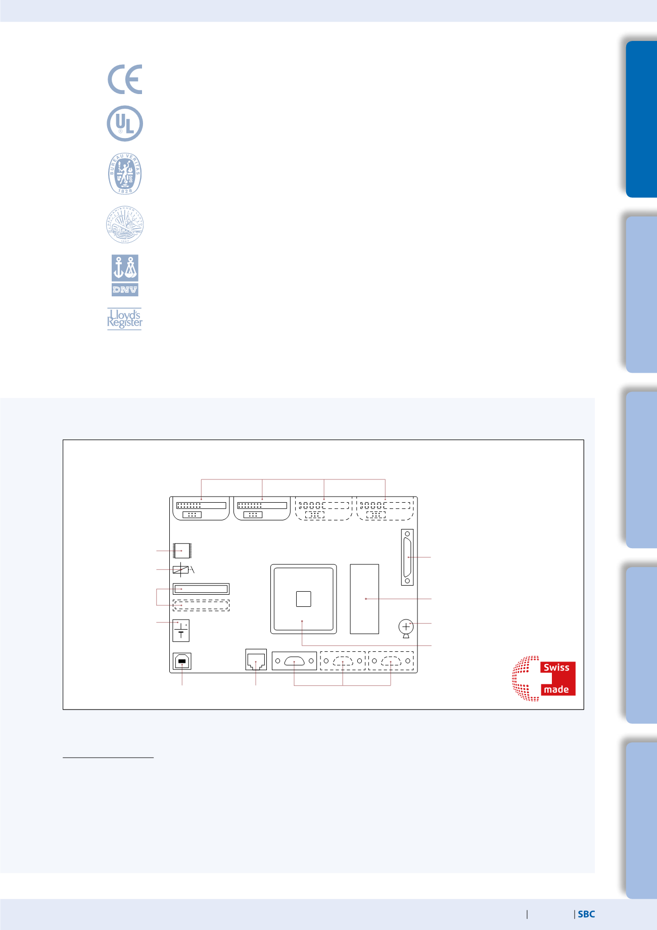
Saia PCD® hardware:
Overview of the core elements of a Saia PCD® controller
Watchdog
1…2 slots for PCD7.Rxxxx
memory card
24 VDC
power supply
USB
interface
Ethernet
interface
1…3 serial interfaces
Expansion with additional I/O modules
(with the exception of PCD1.M2/expansions
PCDx.C with PCDx.I/O/B/W) up to max. 1023
data points
Memory for user program
128 kB–2 MB
66–233 MHz
Coldfire processor
Battery/SuperCap
Two slots for memory for PCD1.M2 / four slots for memory (PCDx.R),
communication (PCDx.F) or I/O modules (PCDx.I/O/B/W)
Real time clock


