9
saia-pcd.com
IIIIIIIIIIIIIIIIIIIIIII
IIIIIIIIIIIIIIIIIIIIIII
Automation stations – the basics
5
4
3
2
1
Cabinet
components
Dedicated
room controller
HMI Visualization
and operating
Automation
stations
Consumption data
acquisition
Basic configuration of the Saia PCD® CPU modules
Standards
Saia PCD® controllers comply with the IEC EN 61131-2 standard in terms of design and produc-
tion quality. This standard defines in 150 pages how electronic items should be developed and
produced to satisfy PLC quality requirements. All the important topics for the applications are
covered: From the environmental conditions (temperature, humidity, vibration), to functionality
(fluctuations in the power supply, interruptions) and electromagnetic compliance depending on
the area of application.
Since application settings all too often fail to behave in accordance with the standards, we made
control technology more robust against interference than the CE standard requires. The majority
of Saia PCD®s are also approved for maritime applications, where increased demands are made
on the devices.
The quality and robustness of the Saia PCD® controllers can also be seen in MTBF values, in the
rates of returns from the field and in the feedback from the customer satisfaction surveys that we
regularly carry out.
You can find further information on this on page 18.
Common properties
`
USB interface for configuration, programming and commissioning
`
Ethernet interface with all the important web/IT protocols, including those for PG5 communication
`
At least one serial interface on-board (Saia PCD3.M5/6: 3×)
`
24 VDC power supply
`
Data remanence through battery and/or SuperCap
`
Watchdog and fast interrupt inputs on the main CPU
`
Slots for intelligent communication or memory modules
`
Can be extended in a modular way (apart from Saia PCD1.M) to max. 1,023 central data points
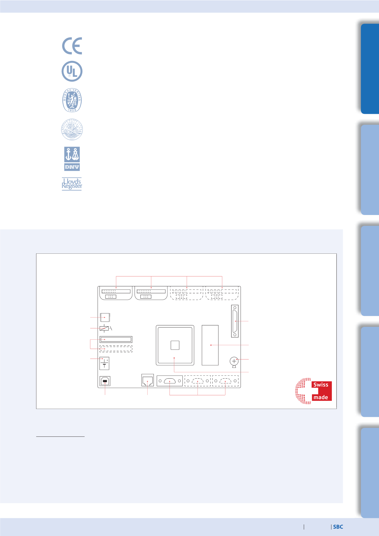
Saia PCD® hardware
S
Overview of the core elements of a Saia PCD® controller
Watchdog
1…2 slots for PCD7.Rxxxx
memory card
24 VDC power supply
USB
interface
Ethernet
interface
1…3 serial interfaces
Extension with additional I/O modules
(apart from PCD1.M2) (extensions to PCDx.C
with PCDx.E/A/B/W) to max. 1,023 data points
Memory for user program
128 kB–2 MB
66–233 MHz
ColdFire processor
Battery/SuperCap
Four (or two in the case of PCD1.M2) slots
for memory (PCDx.R), communication (PCDx.F)
or I/O modules (PCDx.E/A/B/W)
Real-time clock


