56
saia-pcd.com
PCD
2
PGU
X2
X8
X5
16
32
48
112
64
96
80
O C
Error
Run
Halt
WD
24VDC
Battery
X7
X6
X4
X3
SlotA#1
SlotA#2
PCD2.M5540
S1
X1
MPI
X9
0
RUN
HALT
PCD7.F7500
X10
X1
X2
X3
X4
24VDC
Battery
WD
Run
Halt
Error
0
10 9
19
X5
X6
20
30 29
39
S1
O
C
X8
X7
ETH2
ETH1
USB
S2
254
70
208
X1 X2
M1
Slot A1
X3
X4
M2
X6
X5
Slot A2
Slot C
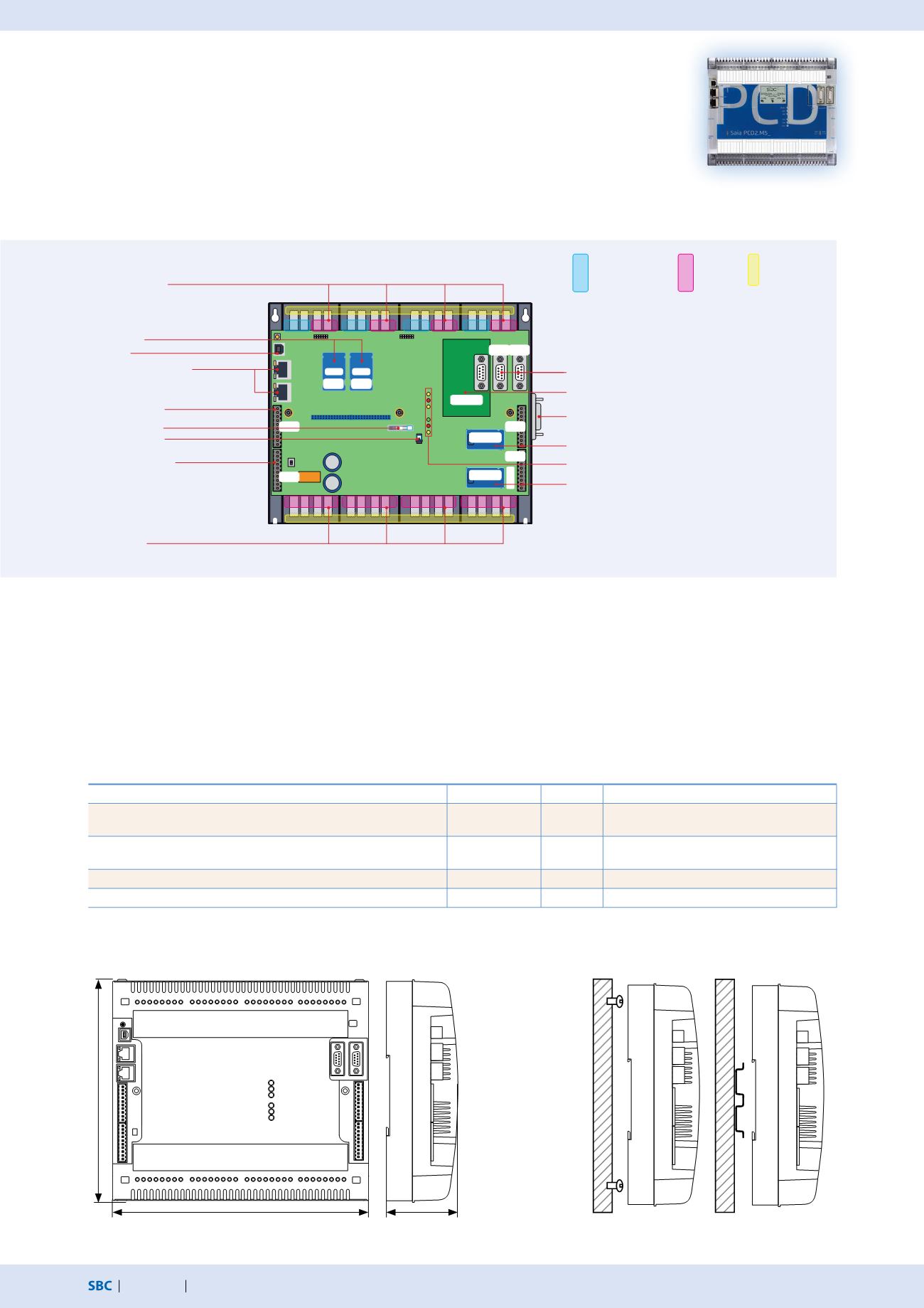
Automation stations – Saia PCD2
Saia PCD2.M5xxx controllers
Due to its flat housing design, the Saia PCD2.M5xxx is ideal for space-saving applications.
The powerful CPU enables the control and regulation functions of complex applications with up
to 1023 central data points. This allows the PCD2 to be expanded for L
on
IP® or BACnet®-compatible
controller using plug-in memory modules. The PCD2 has communication interfaces such as USB,
Ethernet, RS-485 and onboard Automation Server.
System properties
Up to 15 communication interfaces (RS-232, RS-485, etc.)
8 I/O slots that can be expanded using module holders
to max. 64 slots (1023 central data points)
Remote I/O expansion with RIO PCD3.T66x (Ethernet) or
PCD3.T760 (Profi S-IO)
1 MB of program memory
Dimensions
Onboard interfaces of the Saia PCD2.M5xxx
Type
Connection
Port
Transmission rate
RS-232 (serial) or
RS-485 (serial)
X2 (D-Sub)
X5 (terminal)
0
0
≤ 115.2 kbit/s
≤ 115.2 kbit/s
RS-485 (serial) for free protocols or
Profi S-Net / Profibus DP Slave
X1 (D-Sub)
X1 (D-Sub)
3
10
≤ 115.2 kbit/s
≤ 1.5 Mbit/s
Ethernet (2-port switch) (PCD2.M5540 only)
Ethernet
9
10/100 Mbit/s
USB 1.1 (PGU)
USB
---
≤ 12 Mbit/s
Mounting
Automation Server Onboard
Data memory with flash memory modules that
can be expanded to 4 GB
6 fast interrupt/counter inputs on the CPU
Compatible with all PCD3 module holders
8 I/O-module slots 0
…
7
Connection for I/O expansion
I/O 7
I/O 6
I/O 5
I/O 4
I/O 0
I/O 1
I/O 2
I/O 3
Flash cards
USB port
2-port Ethernet switch
(PCD2.M5540 only)
Interrupt inputs
Lithium battery
Onboard interface
and power supply
Run/stop switch
LEDs
C slot for Profibus Master module
Connections for onboard interfaces
Slot for communication module with X3 connection
The same instructions apply as for the PCD3 in
Chapter 1.2 and in the Manual 26-856 regarding
the power supply and the grounding plan.
Slot for communication module with X4 connection
PCD2.M5xxx
Module slot
Module slot
I/O bus for
standard
modules
Fast serial bus (SPI) for
running up to 4 intel-
ligent modules
Ground con-
nection for I/O
modules


