What is the meaning of E-Line RIO – Leds & status specifications
FAQ #101998
Following modules have status visible directly on the device and in the symbol.
This Faq does explain the meaning of each status. This is valid for the following modules. (L-Series)
1.1 General status
1.1.1 LED signalization
Pwr | Steady Green: Device run |
| Off Device stopped |
Com | Steady green: Sbus/Modbus communication ok | Blink red (2hz): autobaud search | off: no communication |
Err |
| Red: Internal error (Flag error) |
|
2.1 Analog inputs
2.1.1 LED signalization
| LEDs State | ||
Input Mode | OFF | ON | Blink |
0…10V | 0…325mV | 0.325…10V | > 10V |
+/-10V | -325mV…325mV | -10…-0.325V 0.325…10V | < -10V > 10V |
0…2k5 | - | Value in range | >2k5 or open * |
0…7k5 | - | Value in range | >7k5 or open * |
0…300k | - | Value in range | >300k or open * |
Pt 1000 | - | Value in range | < -50°C * > 400°C or open |
Ni 1000 | - | Value in range | < -50°C * > 210°C or open |
Ni 1000 L&S | - | Value in range | < -30°C * > 140°C |
*) To avoid error indication (blinking LED) unused inputs should be configured in voltage range (default).
2.1.2 Status register
The analog input status registers are updated cyclically when the firmware read the inputs.
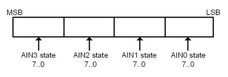
Each register contain 4 analog input states, one byte by channel.
Below for example the AnalogueInputStatus0_3:

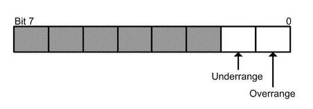
The state register has 2 bits for information about overflow & underflow and the 6 others are reserved

The status is cleared when the input has again a correct value.
2.2 Analog outputs
2.2.1 LED signalization
LEDs State | ||
OFF | ON | Blink |
0…325mV | 0.325…10V | - |
2.3 Digital input
2.3.1 LED signalization
LEDs State | ||
OFF | ON | Blink |
0…5V | 15V…24V | - |
2.4 Relay output
2.4.1 LED signalization
LEDs State | ||
OFF | ON | Blink |
Low | High | - |
Categories
PCD1 / E-Line
Last update: 02.07.2019 13:20
First release: 01.12.2016 09:42
Views: 3
