How is the memory of Windows CE based Web Panels organized?
FAQ #101183
This FAQ describes the architecture of Windows CE based Web Panels (PCD7.D5xxx).
Memory structure of a Saia PCD® Web Panel CE
Saia PCD® CE web panel run with two types of memory: RAM and flash memory.
- The RAM memory is integrated into the web panel and resides on the CPU board.
- The flash memory is realised with a Compact Flash Card (CFC) and is accessible from external via a CFC slot. There are other CE devices which offer also an internal flash memory – Saia PCD® CE web panel realise the whole flash memory with the external CFC. This way, the size of flash memory could be adapted to the application needs.
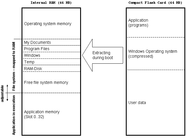
Saia PCD® CE web panel come with 64 MB or 128 MB of internal RAM and a 64 MB or a 128 MB CFC. The below mentioned memory layout ("Windows CE memory architecture") is mapped to the 64 MB of internal RAM. In the internal RAM the operating system and applications are executed. The CFC holds all operating system files, SBC specific extensions like the JVM or S/Web-Connect, other application software and user data.
Start-up and executing Windows CE
In contrast to other Windows CE devices like PDAs, the internal RAM of Saia PCD® web panel is not battery backed-up. Thus after power-on, the panel boots and starts Windows CE from scratch. The Windows CE operating system is stored on the CFC in a couple of compressed files. During start-up, the Windows CE files are extracted into the internal RAM. Finally the operating system runs in the internal RAM. That’s why you loose all made changes like setting IP addresses, short-cuts on the desk-top or registry settings if you switch of the power without launching the "REBOOT" application in the "Lauer EPC manger" (before rebooting it stores registry settings to the CFC).
Basic folders of a Saia PCD® Web Panel CE
During the boot sequence, in one part of the internal RAM (Shared Memory) a file system is created: the windows and program files folders, the "My documents" and temp directories and a "RAM disk". The CFC card is called "Storage Card". If a memory stick is connected to the panel, it’s default name is "Storage Card 2". There is a specialised folder called "Network" which makes all available network connections accessible. Therefore it’s not allocated to RAM or the CFC – it contains links to external resources.
Windows CE memory architecture
Windows CE supports RAM, ROM or flash memory. In today's Windows CE devices you will only find RAM for executing the operating system or applications and flash memory for persistent storing the Windows CE operating system, user installed software applications and user data.
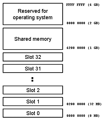
The Windows CE memory management is based on a virtual memory concept. In total a flat 32 bits address space of 4 GB is accessible. As with all virtual memory concepts, the complete address space is normally not covered with real memory. The memory management of the operating system translates the address space to the real equipped memory of the device, which is much smaller in size. This functionality easies software engineering and allows a more efficient use of the memory.
For applications, only the lower 2 GB oft the total address space are available. The upper 2 GB are used by the operating system itself. Also the lower 2 GB applications part is divided into 2 sections: the shared memory and the slot section. The shared memory is mainly used for storing memory-mapped files like the operating system files after boot-up. The slot section is divided into 33 slots of 32 MB each.
Applications (or process) which are executing, get one slot for program and data space. In total, Windows CE can run 32 applications simultaneously. Slot 0 has a special meaning: here resides the actual executed process. If a process becomes active, its slot is mapped to the slot 0 address space and executed. Also the maximum slot size is 32 MB, applications with less memory requirements do not waste unused memory; the operating system maps only the necessary memory to the application slot and saves this way memory for other applications. However, it’s not easy for applications to use more than 32 MB of memory. If necessary, an application can be broken down to 2 processes, occupying 2 slots. But this makes referencing and managing variables complicate and slow. Also using the shared memory does not replace proper stack and heap structures in the assigned single slot. That’s why more or less there is a hard limit of 32 MB for applications in terms of memory. Even if the system is equipped with much more memory it doesn’t help.
Adjusting Windows CE memory
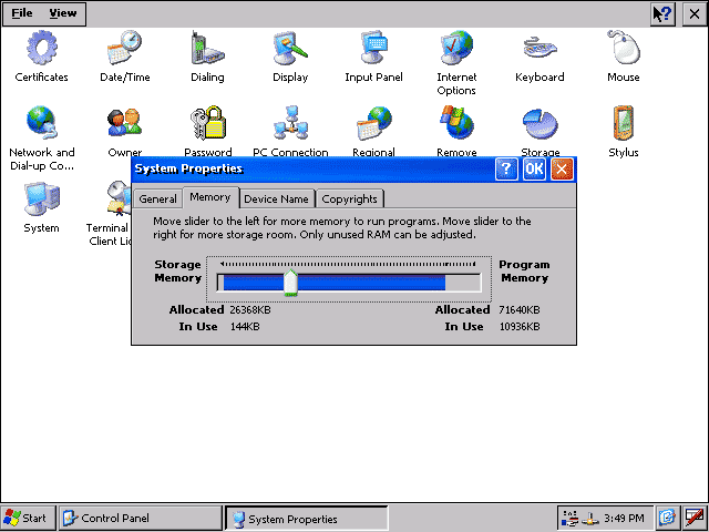
The use of the internal RAM can be adjusted by the user within certain limits. Basically there are two big memory sections: storage memory and program memory. Storage memory describes more or less the shared memory part of internal RAM. Windows CE uses this part mainly to map the RAM based file system. Program memory describes the part of the internal memory where the slots 0 to 32 for applications are mapped.
After opening the control panel windows (Start-Settings-Control Panel), the "System" icon can be selected. In the "System Properties" window, there is a "Memory" tab. It contains a slider with which it’s possible to allocate more memory for storage use (file system) or program use (application execution). The blue bar represents the current available RAM.
Notes
- The screenshot were made using a panel with 128 MByte internal RAM.
- The herein provided information is related to Saia PCD® Windows CE Web Panels. There are other implementations of Windows CE operating systems possible (e.g. memory structure).
Categories
PCD7 / D5xxx (Windows CE)
Last update: 01.06.2015 02:33
First release: 10.04.2009 09:11
Views: 4951
