How to wire a Profibus DP network correctly to a PCD?
FAQ #100164
Depending the PCD type there are up to 3 interfaces to connect the PCD to a Profibus DP or a Profi-S-I/O (or FDL in general) network.
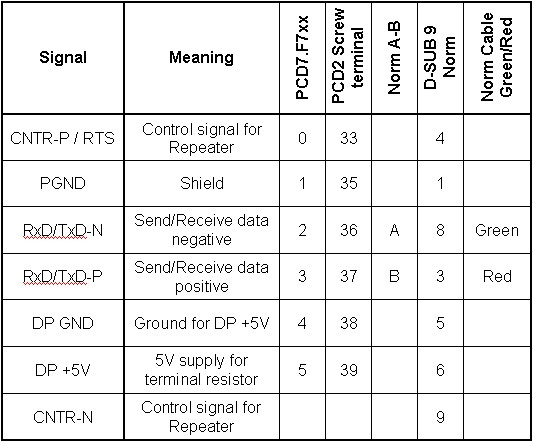
Please consult the table below for the correct connection of the Profibus cables:

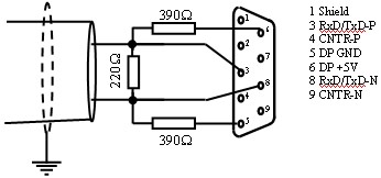
The Profibus network has to be terminated on both sides of it in one of the following ways:
1. Termination boxes that are placed at the begining and end of the line topologie (solution that should be preferd):

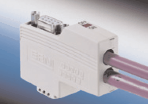
2. For baudrates up to 1.5 Mbaud the termination can also be realized directly on the first and last device of the network. Note that there are also specific connectors with housings with come with the resistors already equipped.

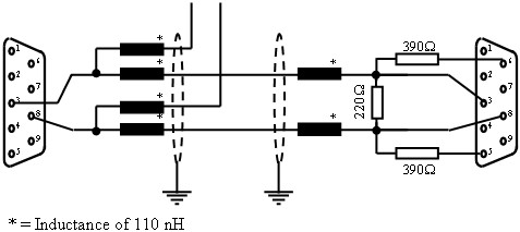
3. For higher baudrates the second solution is not suitable. Inductances has to be add to the termination:

Hint
Connectors with additional service interface D-SUB are very useful for temprarily connecting e.g. an analyzer! We therefore recommend using at least one of these connectors per network.
Categories
PCD7 / Fxxx
PG5 2.0 / Profibus DP
PG5 2.0 / Profi-S-I/O
Last update: 30.05.2015 23:08
First release: 22.06.2004 12:34
Views: 5259
