
-
BIM-Objects for Saia PCD1 E-Line
-
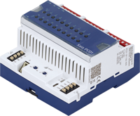
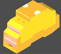
E-Line CPU PCD1.M2220-C15

The Saia PCD® controller PCD1.M2200-C15 functions as a master for the attached modules. Here it can undertake more complex controls and form the interface to the control level.
BIM - Saia PCD1 E-Line CPU
| Tutorial | PCD1.M2220-C15 | BIM - Saia PCD1 E-Line CPU |
E-Line CPU PCD1.M2220-C15
Freely programmable
Supply 24 VAC/VDC
Web and FTP server, filesystem
512 kByte memory for application program
128 kByte FRAM memory for R/F/T/C/DB/Text
128 MByte flash-memory
No battery, but backup of R/F/T/C/DB/Text with FRAM technology (the data are retained in a de-energised state)
2 I/O Slots for PCD2 I/O modules (maximum of 39 I/O's directly on a PCD PCD1.M2200-C15)
1 Slot for 'M' memory module
| PDS - xlsx |

|
0.31 MB | Download | ||
| Revit-file - .rfa - Revision: - |
|
.zip | 0.54 MB | Download | |
| CREO-export - .sat |
|
.zip | 0.09 MB | Download | |
| Step-file - .step |
|
.zip | 0.24 MB | Download | |
| Step-file - .stp |
|
.zip | 0.10 MB | Download | |
| DXG-file - .dxf |
|
.zip | 0.02 MB | Download | |
| IFC-file - .ifc |
|
.zip | 0.05 MB | Download | |
| IGES-file - .iges |
|
.zip | 0.10 MB | Download | |
| IGS-file - .igs |
|
.zip | 0.10 MB | Download | |
| RHINO-file - .3dm |
|
.zip | 0.21 MB | Download | |
| X3D-file - .x3d |
|
.zip | 0.01 MB | Download | |
| DS -31-100 ENG |
|
1.01 MB | Download | ||
| DS -31-100 FRA |

|
1.01 MB | Download | ||
| DS -31-100 GER |

|
1.01 MB | Download | ||
| DS -31-100 ITA |

|
1.01 MB | Download | ||
| Manual - 27-640 ENG |
|
7.97 MB | Download | ||
| Manual - 27-640 FRA |
|
7.91 MB | Download | ||
| Manual - 27-640 GER |
|
8.03 MB | Download | ||
| Manual - 27-640 ITA |
|
7.91 MB | Download |
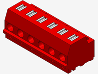
E-Line: S-Serie
BIM - PCD1.A1000-A20
| Tutorial | E-Line - S-Serie | BIM - PCD1.A1000-A20 |
E-Line S-Serie digital output module
Manual override operating level for all outputs
Status LED for outputs
Supply 24 VDC
- 10 digital outputs 24 VDC (12…32 VDC/0.5 A)
- 1 interface RS-485 (S-Bus and Modbus)
- 1 USB service interface
| PDS - xlsx |
|
0.31 MB | Download | ||
| Revit-file - .rfa - Version: a |
|
.zip | 0.29 MB | Download | |
| CREO-export - .sat |
|
.zip | 0.02 MB | Download | |
| Step-file - .step |
|
.zip | 0.02 MB | Download | |
| Step-file - .stp |
|
.zip | 0.02 MB | Download |
BIM - PCD1.A2000-A20
| Tutorial | E-Line - S-Serie | BIM - PCD1.A2000-A20 |
E-Line S-Serie digital output module
manual override operating level for all outputs
status LED for outputs
supply 24 VDC
- 6 relay normally open 230 VAC / 30 VDC, 16 A (resistive load)
- 1 interface RS-485 (S-Bus and Modbus)
- 1 USB Service interface
| PDS - xlsx |
|
0.31 MB | Download | ||
| Revit-file - .rfa - Version: a |
|
.zip | 0.29 MB | Download | |
| CREO-export - .sat |
|
.zip | 0.02 MB | Download | |
| Step-file - .step |
|
.zip | 0.02 MB | Download | |
| Step-file - .stp |
|
.zip | 0.02 MB | Download |
BIM - PCD1.B1100-A20
| Tutorial | E-Line - S-Serie | BIM - PCD1.B1100-A20 |
E-Line S-Serie Digital input/output module
manual override operating level for all outputs
status LED for inputs and outputs
supply 24 VDC
- 4 digital inputs; 24 VDC (source operation)
- 10 relay (6 normally open/ 4 changeover) 250 VAC / 30 VDC, 5 A (DC1)
- 1 interface RS-485 (S-Bus and Modbus)
- 1 USB Service interface
| PDS - xlsx |
|
0.15 MB | Download | ||
| Revit-file - .rfa - Version: a |
|
.zip | 0.29 MB | Download | |
| CREO-export - .sat |
|
.zip | 0.02 MB | Download | |
| Step-file - .step |
|
.zip | 0.02 MB | Download | |
| Step-file - .stp |
|
.zip | 0.02 MB | Download |
BIM - PCD1.B1120-A20
| Tutorial | E-Line - S-Serie | BIM - PCD1.B1120-A20 |
E-Line S-Serie Digital input/output module
manual override operating level for all outputs
status LED for inputs and outputs
supply 24 VDC
- 16 digital inputs; 24 VDC (source operation)
- 4 relay changeover 250 VAC / 30 VDC, 5 A (DC1)
- 1 interface RS-485 (S-Bus and Modbus)
- 1 USB Service interface
| PDS - xlsx |
|
0.15 MB | Download | ||
| Revit-file - .rfa - Version: a |
|
.zip | 0.43 MB | Download | |
| CREO-export - .sat |
|
.zip | 0.02 MB | Download | |
| Step-file - .step |
|
.zip | 0.02 MB | Download | |
| Step-file - .stp |
|
.zip | 0.02 MB | Download |
BIM - PCD1.B5000-A20
| Tutorial | E-Line - S-Serie | BIM - PCD1.B5000-A20 |
E-Line S-Serie Digital input/output module
manual override operating level for all outputs
status LED for inputs and outputs
supply 24 VDC
- 6 Digital inputs 115…230 VAC
- 3 relay normally open 230 VAC / 30 VDC, 6 A (resistive load)
- 1 interface RS-485 (S-Bus and Modbus)
- 1 USB Service interface
| PDS - xlsx |
|
0.31 MB | Download | ||
| Revit-file - .rfa - Version: a |
|
.zip | 0.43 MB | Download | |
| CREO-export - .sat |
|
.zip | 0.02 MB | Download | |
| Step-file - .step |
|
.zip | 0.02 MB | Download | |
| Step-file - .stp |
|
.zip | 0.02 MB | Download |
BIM - PCD1.B5010-A20
| Tutorial | E-Line - S-Serie | BIM - PCD1.B5010-A20 |
E-Line S-Serie Digital input/output module
manual override operating level for all outputs
status LED for inputs and outputs
supply 24 VDC
- 6 Digital inputs 24 VAC/DC
- 3 relay normally open 230 VAC / 30 VDC, 6 A (resistive load)
- 1 interface RS-485 (S-Bus and Modbus)
- 1 USB Service interface
| PDS - xlsx |
|
0.15 MB | Download | ||
| Revit-file - .rfa - Version: a |
|
.zip | 0.43 MB | Download | |
| CREO-export - .sat |
|
.zip | 0.02 MB | Download | |
| Step-file - .step |
|
.zip | 0.02 MB | Download | |
| Step-file - .stp |
|
.zip | 0.02 MB | Download |
BIM - PCD1.E1000-A10
| Tutorial | E-Line - S-Serie | BIM - PCD1.E1000-A10 |
E-Line S-Serie Digital input module
status LED for inputs
supply 24 VDC
- 12 Digital inputs 24 VDC (source operation)
- 1 interface RS-485 (S-Bus and Modbus)
- 1 USB service interface
| PDS - xlsx |
|
0.31 MB | Download | ||
| Revit-file - .rfa - version: a |
|
.zip | 0.43 MB | Download | |
| CREO-export - .sat |
|
.zip | 0.02 MB | Download | |
| Step-file - .step |
|
.zip | 0.02 MB | Download | |
| Step-file - .stp |
|
.zip | 0.02 MB | Download |
BIM - PCD1.G2000-A20
| Tutorial | E-Line - S-Serie | BIM - PCD1.G2000-A20 |
E-Line S-Serie combined input/output module
manual override operating level for all outputs
status LED for inputs and outputs
supply 24 VDC
- 6 universal digital/analogue inputs
- digital inputs 24 VDC
- analoque inputs 12 bits
0…10 V, Pt/Ni 1000, Ni 1000 L&S, NTC,
0…2500 Ohm, 0…7500 Ohm, 0…300 kOhm
- 2 analogue outputs 10 bits, 0…10 V
- 2 triac outputs 24 VAC/1 A or 230 VAC/1 A
- 1 interface RS-485 (S-Bus and Modbus)
- 1 USB Service interface
| PDS - xlsx |
|
0.31 MB | Download | ||
| Revit-file - .rfa - Version: A |
|
.zip | 0.30 MB | Download | |
| CREO-export - .sat |
|
.zip | 0.02 MB | Download | |
| Step-file - .step |
|
.zip | 0.02 MB | Download | |
| Step-file - .stp |
|
.zip | 0.02 MB | Download |
BIM - PCD1.G2100-A10
| Tutorial | E-Line - S-Serie | BIM - PCD1.G2100-A10 |
E-Line S-Serie combined input/output module
manual override operating level for all outputs
status LED for inputs and outputs
supply 24 VDC
- 8 universal digital/analogue inputs
- digital inputs 24 VDC
- analoque inputs 12 bits
0…10 V, Pt/Ni 1000, Ni 1000 L&S, NTC,
0…2500 Ohm, 0…7500 Ohm, 0…300 kOhm
- 1 interface RS-485 (S-Bus and Modbus)
- 1 USB Service interface
| PDS - xlsx |
|
0.15 MB | Download | ||
| Revit-file - .rfa - Version: a |
|
.zip | 0.43 MB | Download | |
| CREO-export - .sat |
|
.zip | 0.02 MB | Download | |
| Step-file - .step |
|
.zip | 0.02 MB | Download | |
| Step-file - .stp |

|
.zip | 0.02 MB | Download |
BIM - PCD1.G2200-A20
| Tutorial | E-Line - S-Serie | BIM - PCD1.G2200-A20 |
E-Line S-Serie combined input/output module
manual override operating level for all outputs
status LED for inputs and outputs
supply 24 VDC
- 8 universal digital/analogue inputs
- digital inputs 24 VDC
- analoque inputs 12 bits
0…10 V, Pt/Ni 1000, Ni 1000 L&S, NTC,
0…2500 Ohm, 0…7500 Ohm, 0…300 kOhm
- 4 analogue outputs 10 bits, 0…10 V
- 1 interface RS-485 (S-Bus and Modbus)
- 1 USB Service interface
| PDS - xlsx |
|
0.31 MB | Download | ||
| Revit-file - .rfa - Version: a |
|
.zip | 0.43 MB | Download | |
| CREO-export - .sat |
|
.zip | 0.02 MB | Download | |
| Step-file - .step |
|
.zip | 0.02 MB | Download | |
| Step-file - .stp |
|
.zip | 0.02 MB | Download | |
| DXG-file - .dxf |
|
.zip | 0.01 MB | Download | |
| IFC-file - .ifc |
|
.zip | 0.02 MB | Download | |
| IGES-file - .iges |
|
.zip | 0.02 MB | Download | |
| IGES-file - .igs |
|
.zip | 0.02 MB | Download | |
| RHINO-file - .3dm |
|
.zip | 0.04 MB | Download | |
| X3D-file - .x3d |
|
.zip | 0.01 MB | Download | |
| DS - 31-151 - ENG |
|
1.58 MB | Download | ||
| DS - 31-151 - FRA |
|
1.61 MB | Download | ||
| DS - 31-151 - GER |
|
1.87 MB | Download | ||
| DS - 31-151 - ITA |
|
1.86 MB | Download |
BIM - PCD1.W5200-A20
| Tutorial | E-Line - S-Serie | BIM - PCD1.W5200-A20 |
E-Line S-Serie analogue output module
manual override operating level for all outputs
status LED for outputs
supply 24 VDC
- 8 analogue outputs 10 bits, 0…10 V
- 1 interface RS-485 (S-Bus and Modbus)
- 1 USB service interface
| PDS - xlsx |
|
0.31 MB | Download | ||
| Revit-file - .rfa - Version: a |
|
.zip | 0.43 MB | Download | |
| CREO-export - .sat |
|
.zip | 0.02 MB | Download | |
| Step-file - .step |
|
.zip | 0.02 MB | Download | |
| Step-file - .stp |
|
.zip | 0.02 MB | Download |
E-Line: L-Serie

BIM - PCD1.B1000-A20
| Tutorial | E-Line - L-Serie | BIM - PCD1.B1000-A20 |
E-Line digital input/output module
manual override operating level for all outputs
status LED for inputs and outputs
supply 24 VDC
- 4 digital inputs 24 VDC (source operation)
- 6 relay normally open 230 VAC / 30 VDC, 4 A (resistive load)
- 4 relay changeover 230 VAC / 30 VDC, 4 A (resistive load)
- 1 interface RS-485 (S-Bus and Modbus)
| PDS - xlsx |
|
0.31 MB | Download | ||
| Revit-file - .rfa - Version: - |
|
.zip | 0.28 MB | Download | |
| CREO-export - .sat |
|
.zip | 0.01 MB | Download | |
| Step-file - .step |
|
.zip | 0.01 MB | Download | |
| Step-file - .stp |
|
.zip | 0.01 MB | Download |
BIM - PCD1.B1010-A20
| Tutorial | E-Line - L-Serie | BIM - PCD1.B1010-A20 |
E-Line digital input/output module
manual override operating level for all outputs
status LED for inputs and outputs
supply 24 VDC
- 24 digital inputs 24 VDC (source operation)
- 6 relay normally open 230 VAC / 30 VDC, 4 A (resistive load)
- 4 relay changeover 230 VAC / 30 VDC, 4 A (resistive load)
- 1 interface RS-485 (S-Bus and Modbus)
| PDS - xlsx |
|
0.31 MB | Download | ||
| Revit-file - .rfa - Version: - |
|
.zip | 0.28 MB | Download | |
| CREO-export - .sat |
|
.zip | 0.01 MB | Download | |
| Step-file - .step |
|
.zip | 0.01 MB | Download | |
| Step-file - .stp |
|
.zip | 0.01 MB | Download |
BIM - PCD1.B1020-A20
| Tutorial | E-Line - L-Serie | BIM - PCD1.B1020-A20 |
E-Line digital input/output module
manual override operating level for all outputs
status LED for inputs and outputs
supply 24 VDC
- 16 digital inputs 24 VDC (source operation)
- 4 relay changeover 230 VAC / 30 VDC, 4 A (resistive load)
- 1 interface RS-485 (S-Bus and Modbus)
| PDS - xlsx |
|
0.31 MB | Download | ||
| Revit-file - .rfa - Version: - |
|
.zip | 0.28 MB | Download | |
| CREO-export - .sat |
|
.zip | 0.01 MB | Download | |
| Step-file - .step |
|
.zip | 0.01 MB | Download | |
| Step-file - .stp |
|
.zip | 0.01 MB | Download |
BIM - PCD1.G5000-A20
| Tutorial | E-Line - L-Serie | BIM - PCD1.G5000-A20 |
E-Line combined input/output module
manual override operating level for all outputs
status LED for inputs and outputs
supply 24 VDC
- 16 digital inputs 24 VDC (source operation)
- 4 relay normally open 230 VAC / 30 VDC, 4 A (resistive load)
- 4 relay changeover 230 VAC / 30 VDC, 4 A (resistive load)
- 8 analogue inputs 12 bits
0…10 V, Pt/Ni 1000, Ni 1000 L&S, NTC, 0…2500 Ohm, 0…7500 Ohm, 0…300 kOhm
- 4 analogue outputs 10 bits, 0…10 V (10 mA max.)
- 1 interface RS-485 (S-Bus and Modbus)
| PDS - xlsx |
|
0.31 MB | Download | ||
| Revit-file - .rfa - Version: - |
|
.zip | 0.29 MB | Download | |
| CREO-export - .sat |
|
.zip | 0.01 MB | Download | |
| Step-file - .step |
|
.zip | 0.01 MB | Download | |
| Step-file - .stp |
|
.zip | 0.01 MB | Download |
BIM - PCD1.G5010-A20
| Tutorial | E-Line - L-Serie | BIM - PCD1.G5010-A20 |
E-Line combined input/output module
manual override operating level for all outputs
status LED for inputs and outputs
supply 24 VDC
- 12 digital inputs 24 VDC (source operation)
- 4 relay changeover 230 VAC / 30 VDC, 4 A (resistive load)
- 12 analogue inputs 12 bits
0…10 V, Pt/Ni 1000, Ni 1000 L&S, NTC, 0…2500 Ohm, 0…7500 Ohm, 0…300 kOhm
- 8 analogue outputs 10 bits, 0…10 V (10 mA max.)
- 1 interface RS-485 (S-Bus and Modbus)
| PDS - xlsx |
|
0.31 MB | Download | ||
| Revit-file - .rfa - Version: - |
|
.zip | 0.28 MB | Download | |
| CREO-export - .sat |
|
.zip | 0.01 MB | Download | |
| Step-file - .step |
|
.zip | 0.01 MB | Download | |
| Step-file - .stp |
|
.zip | 0.01 MB | Download |
BIM - PCD1.G5020-A20
| Tutorial | E-Line - L-Serie | BIM - PCD1.G5020-A20 |
E-Line combined input/output module
manual override operating level for all outputs
status LED for inputs and outputs
supply 24 VDC
- 8 digital inputs 24 VDC (source operation)
- 4 relay changeover 230 VAC / 30 VDC, 4 A (resistive load)
- 16 analogue inputs 12 bits
0…10 V, Pt/Ni 1000, Ni 1000 L&S, NTC, 0…2500 Ohm, 0…7500 Ohm, 0…300 kOhm
- 4 analogue outputs 10 bits, 0…10 V (10 mA max.)
- 1 interface RS-485 (S-Bus and Modbus)
| PDS - xlsx |
|
0.31 MB | Download | ||
| Revit-file - .rfa - Version: - |
|
.zip | 0.29 MB | Download | |
| CREO-export - .sat |
|
.zip | 0.01 MB | Download | |
| Step-file - .step |
|
.zip | 0.01 MB | Download | |
| Step-file - .stp |
|
.zip | 0.01 MB | Download |
E-Line: programmable modules

BIM - Programmable E-Line DALI module
| Tutorial | PCD1.F2611-C15 | BIM - Programmable E-Line DALI module |
Saia PCD® E-Line programmable modules
Programmable E-Line DALI module for up to 64 DALI ballasts with integrated DALI-Bus power supply supply 24 VAC/VDC 4 digital inputs 24 VAC/VDC 3 interfaces: RS-485 (S-Bus), auxiliary RS-485, uUSB for PG5
| Revit-file - .rfa - Revision: - |
|
|
Download | ||
| CREO-export - .sat |
|
.zip | 0.21 MB | Download | |
| Step-file - .step |
|
.zip | 0.45 MB | Download | |
| Step-file - .stp |
|
.zip | 0.19 MB | Download | |
| DXF-file - .dxf |
|
.zip | 0.14 MB | Download | |
| IFC-file - .ifc |
|
.zip | 0.34 MB | Download | |
| IGES-file - .iges |
|
.zip | 0.20 MB | Download | |
| IGS-file - .igs |
|
.zip | 0.20 MB | Download | |
| RHINO-file - .3dm |
|
.zip | 0.53 MB | Download | |
| X3D-file - .x3d |
|
.zip | 0.10 MB | Download | |
| Data sheet 31-112 ENG |
|
1.33 MB | Download | ||
| Data sheet 31-112 FRA |
|
1.33 MB | Download | ||
| Data sheet 31-112 GER |
|
1.34 MB | Download | ||
| Data sheet 31-112 ITA |
|
1.33 MB | Download |
BIM - Programmable E-Line DALI module
| Tutorial | PCD1.T4850-RF | BIM - Programmable E-Line DALI module |
Saia PCD® E-Line programmable modules
RF-Modem for Modbus and S-Bus
| Revit-file - .rfa - Revision: - |
|
|
Download | ||
| CREO-export - .sat |
|
|
.zip | 0.21 MB | Download |
| STEP-file - .step |
|
|
.zip | 0.44 MB | Download |
| STP-file - .stp |
|
|
.zip | 0.44 MB | Download |
| DXF-file - .dxf |
|
|
.zip | 0.44 MB | Download |
| IFC-file - .ifc |
|
|
.zip | 0.35 MB | Download |
| IGES-file - .iges |
|
|
.zip | 0.20 MB | Download |
| IGS-file - .igs |
|
|
.zip | 0.20 MB | Download |
| RHINO-file - .3dm |
|
|
.zip | 0.51 MB | Download |
| X3D-file - .x3d |
|
|
.zip | 0.10 MB | Download |
| Data sheet 31-016 ENG |
|
|
1.06 MB | Download | |
| Data sheet 31-016 FRA |
|
|
1.13 MB | Download | |
| Data sheet 31-016 GER |
|
|
1.13 MB | Download | |
| Data sheet 31-016 ITA |
|
|
1.15 MB | Download | |
| Leaflet - 26-012 |
|
|
0.48 MB | Download |
E-Line: programmable room control modules
BIM - Programmable E-Line DALI module
| Tutorial | PCD1.G1100-C15 | BIM - Programmable E-Line DALI module |
Saia PCD® E-Line programmable modules
Programmable E-Line input/output module for light and sunblind control
supply 24 VAC/VDC 4 digital inputs 24 VAC/VDC 2 relay changeover 230 VAC / 30 VDC, 8 A, max. inrush current 15 A, incl. galvanically isolated current measurement 2 analogue outputs 12 bits, 0…10 V (3 mA max.) 2 interfaces: RS-485 (S-Bus), uUSB for PG5
| Revit-file - .rfa - Revision: - |
|
|
Download | ||
| CREO-export - .sat |
|
.zip | 0.22 MB | Download | |
| STEP-file - .step |
|
.zip | 0.45 MB | Download | |
| STP-file - .stp |
|
.zip | 0.19 MB | Download | |
| DXF-file - .dxf |
|
.zip | 0.14 MB | Download | |
| IFC-file - .ifc |
|
.zip | 0.35 MB | Download | |
| IGES-file - .iges |
|
.zip | 0.21 MB | Download | |
| IGS-file - .igs |
|
.zip | 0.21 MB | Download | |
| RHINO-file - .3dm |
|
.zip | 0.53 MB | Download | |
| X3D-file - .x3d |
|
.zip | 0.10 MB | Download | |
| Data sheet 31-111 ENG |
|
1.23 MB | Download | ||
| Data sheet 31-112 FRA |
|
1.22 MB | Download | ||
| Data sheet 31-111 GER |
|
1.22 MB | Download | ||
| Data sheet 31-111 ITA |
|
1.20 MB | Download | ||
| Data sheet 26-584 ENG |
|
0.56 MB | Download | ||
| Data sheet 26-584 FRA |
|
0.56 MB | Download | ||
| Data sheet 26-584 GER |
|
0.56 MB | Download | ||
| Data sheet 26-584 ITA |
|
0.56 MB | Download |
BIM - E-Line room control module
| Tutorial | PCD1.G3600-C15 | BIM - E-Line room control module |
Programmable E-Line input/output module
for room automation
supply 24 VAC/VDC
- 8 digital inputs 24 VAC/VDC
- 3 relay changeover 230 VAC / 30 VDC, 6 A, max. inrush current 15 A
- 1 relay changeover 230 VAC / 30 VDC, 10 A, max. inrush current 65 A
- 4 triac outputs 24 VCA/1A or 230 VAC/1 A
- 4 analogue inputs 12 bits
0…10 V, ±10 V, 0(4)…20 mA, Pt/Ni 1000, NTC, 0…2500 Ohm, 0…7500 Ohm, 0…300 kOhm
- 4 analogue outputs 12 bits, 0…10 V (3 mA max.)
- 3 interfaces: RS-485 (S-Bus), USB & NFC (service)
| PDS - xlsx |
|
|
0.31 MB | Download | |
| Revit-file - .rfa - Version: - |
|
|
.zip | 0.29 MB | Download |
| CREO-export - .sat |
|
|
.zip | 0.01 MB | Download |
| Step-file - .step |
|
|
.zip | 0.01 MB | Download |
| Step-file - .stp |
|
|
.zip | 0.01 MB | Download |
BIM - E-Line room control module
| Tutorial | PCD1.G3601-C15 | BIM - E-Line room control module |
Programmable E-Line input/output module for room automation with auxiliary RS-485 interface
supply 24 VAC/VDC
- 8 digital inputs 24 VAC/VDC
- 3 relay changeover 230 VAC / 30 VDC, 6 A, max. inrush current 15 A
- 1 relay changeover 230 VAC / 30 VDC, 10 A, max. inrush current 65 A
- 4 triac outputs 24 VCA/1A or 230 VAC/1 A
- 4 analogue inputs 12 bits
0…10 V, ±10 V, 0(4)…20 mA, Pt/Ni 1000, NTC, 0…2500 Ohm, 0…7500 Ohm, 0…300 kOhm
- 4 analogue outputs 12 bits, 0…10 V (3 mA max.)
- 4 interfaces: RS-485 (S-Bus), auxiliary RS-485, USB & NFC (service)
| PDS - xlsx |
|
|
0.31 MB | Download | |
| Revit-file - .rfa - Version: - |
|
|
.RFA | 0.32 MB | Download |
| CREO-export - .sat |
|
|
.zip | 0.01 MB | Download |
| Step-file - .step |
|
|
.zip | 0.01 MB | Download |
| Step-file - .stp |
|
|
.zip | 0.01 MB | Download |
BIM - Programmable E-Line DALI module
| Tutorial | PCD1.W5300-C15 | BIM - Programmable E-Line DALI module |
Saia PCD® E-Line programmable modules
Programmable E-Line input/output module for analogue applications
supply 24 VAC/VDC 4 analogue inputs 12 bits 0…10 V, ±10 V, 0(4)…20 mA, Pt/Ni 1000, NTC, 0…2500 Ohm, 0…7500 Ohm, 0…300 kOhm 4 analogue outputs 12 bits, 0…10 V (4 mA max.) 2 interfaces: RS-485 (S-Bus), micro USB for PG5
| Revit-file - .rfa - Revision: - |
|
|
Download | ||
| CREO-export - .sat |
|
.zip | 0.22 MB | Download | |
| STEP-file - .step |
|
.zip | 0.46 MB | Download | |
| STP-file - .stp |
|
.zip | 0.20 MB | Download | |
| DXF-file - .dxf |
|
.zip | 0.14 MB | Download | |
| IFC-file - .ifc |
|
.zip | 0.37 MB | Download | |
| IGES-file - .iges |
|
.zip | 0.21 MB | Download | |
| IGS-file - .igs |
|
.zip | 0.21 MB | Download | |
| RHINO-file - .3dm |
|
.zip | 0.55 MB | Download | |
| X3D-file - .x3d |
|
.zip | 0.11 MB | Download | |
| Data sheet 31-113 ENG |
|
1.11 MB | Download | ||
| Data sheet 31-113 FRA |
|
1.13 MB | Download | ||
| Data sheet 31-113 GER |
|
0.97 MB | Download | ||
| Data sheet 31-113 ITA |
|
1.11 MB | Download |
Accessories for Saia PCD E-Line
BIM - Saia PCD® E-Line Plug-in Terminal block
| Tutorial | 3 230 4321-003-S | BIM - Saia PCD® E-Line Plug-in Terminal block |
Saia PCD® E-Line Plug-in Terminal block
Plug-in spring terminal block 6-pole, set of 6 pieces for Saia PCD® E-Line S and L Series
| Revit-file - .rfa - Revision: - |
|
|
Download | ||
| CREO-export - .sat |
|
.zip | 0.03 MB | Download | |
| STEP-file - .step |
|
.zip | 0.08 MB | Download | |
| STP-file - .stp |
|
.zip | 0.03 MB | Download | |
| DXF-file - .dxf |
|
.zip | 0.03 MB | Download | |
| IFC-file - .ifc |
|
.zip | 0.07 MB | Download | |
| IGES-file - .iges |
|
.zip | 0.04 MB | Download | |
| IGS-file - .igs |
|
.zip | 0.04 MB | Download | |
| RHINO-file - .3dm |
|
.zip | 0.08 MB | Download | |
| X3D-file - .x3d |
|
.zip | 0.02 MB | Download |